
Topology optimization is associated with extreme design freedom and thus extreme performance, but the resulting designs are often incompatible with conventional manufacturing techniques. The development of manufacturing constraints for topology optimization is an active research topic. The COMSOL Multiphysics® software supports milling constraints, and in this blog post we will explain how to use such functionality and show examples.
Topology Optimization
Using the density method is the most common approach for performing topology optimization, and it’s implemented in the Density Model feature in COMSOL Multiphysics. The most common applications are in the field of structural mechanics, where regularization is typically needed to obtain meaningful results. The Density Model feature supports regularization using a partial differential equation (PDE)-based filter, called a Helmholtz filter. The figure below illustrates the difference between parameter, shape, and topology optimization for a structural mechanics example. For more details, refer to our previous blog post on topology optimization, “Performing Topology Optimization with the Density Method”.
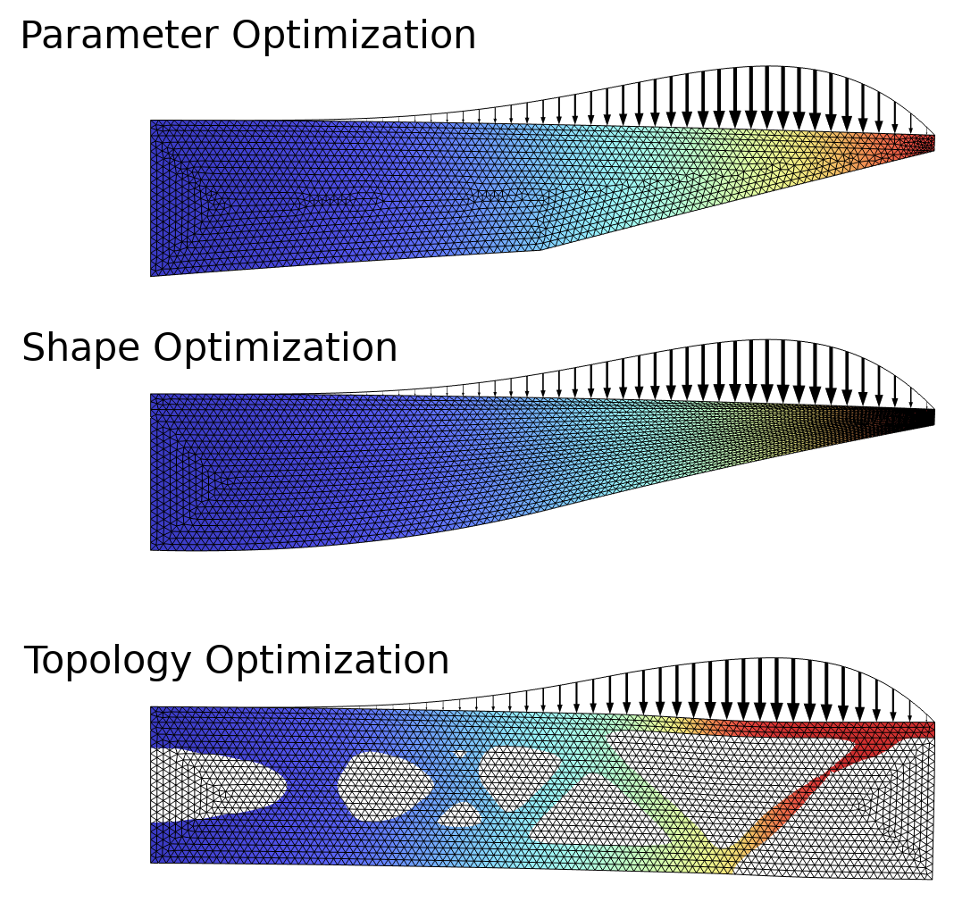
Figure 1. This example, the Design Optimization of a Beam model, solves a problem from structural mechanics using parameter, shape, and topology optimization. The objective is to minimize the mass subjected to a constraint on the displacement in the upper-right point. Only topology optimization is able to introduce holes in the design.
Milling Constraints
The implementation of milling constraints in the Density Model feature follows publications in academic literature (Ref. 1). The basic concept is to use a set of convective equations with convection in the milling directions, \hat{m}_\mathrm{mil}^i:
The first equation is the Helmholtz filter, which uses the control variable field, $\theta_c$, to compute the filtered field, $\theta_f$, which has a minimum length scale of $L_\mathrm{min}$. The convective equation (the second line) sits between the Helmholtz filter and the projection. There is a length scale for the source term, R_\mathrm{mil}, but this can usually be set based on the mesh size. There is also a numerical parameter, $p_\mathrm{mil}$, associated with the aggregation of the milling variables, \theta_m^i. A value of 10 is fine for 2–3 milling directions, but a large number of milling directions can require higher values. The same is true for the projection slope, \beta, which plays a more important role than usual since it’s common for the input to the projection (the third line) to be significantly larger than 1. The projection threshold \theta_\beta is fixed to 0.5. The density is interpolated with the projected field, \theta, while solid isotropic material with penalization (SIMP) interpolation is used for the stiffness (last line, \theta_p). Typically p_\mathrm{SIMP}=3 is chosen to avoid gray scale in the final design, while \theta_\mathrm{min}=10^{-3} is used to ensure robustness if numerical issues cause the projected field to be slightly negative.
We will only consider single material optimization, so the volume V is equivalent to the mass, M, which can be calculated by integrating the projected field and multiplying with the density, \rho:
Introducing milling constraints to the formulation introduces more local minima, and it can be beneficial to use a continuation where series of optimization are solved. This is mostly an issue for three-dimensional problems, so it’s not relevant to the first example we will show here.
Example 1: 2D Beam
The problem formulation is sketched in the figure below, and it’s identical to that of the previous section in the sense that it’s a structural mechanics problem where the objective is to minimize the mass subjected to a constraint in the upper-right point. This time, however, the material cannot be distributed freely since a milling constraint is imposed. There are two milling directions which coincide with the coordinate axes, meaning that material can only be removed by a “subtractive tool” coming from the left or from below.
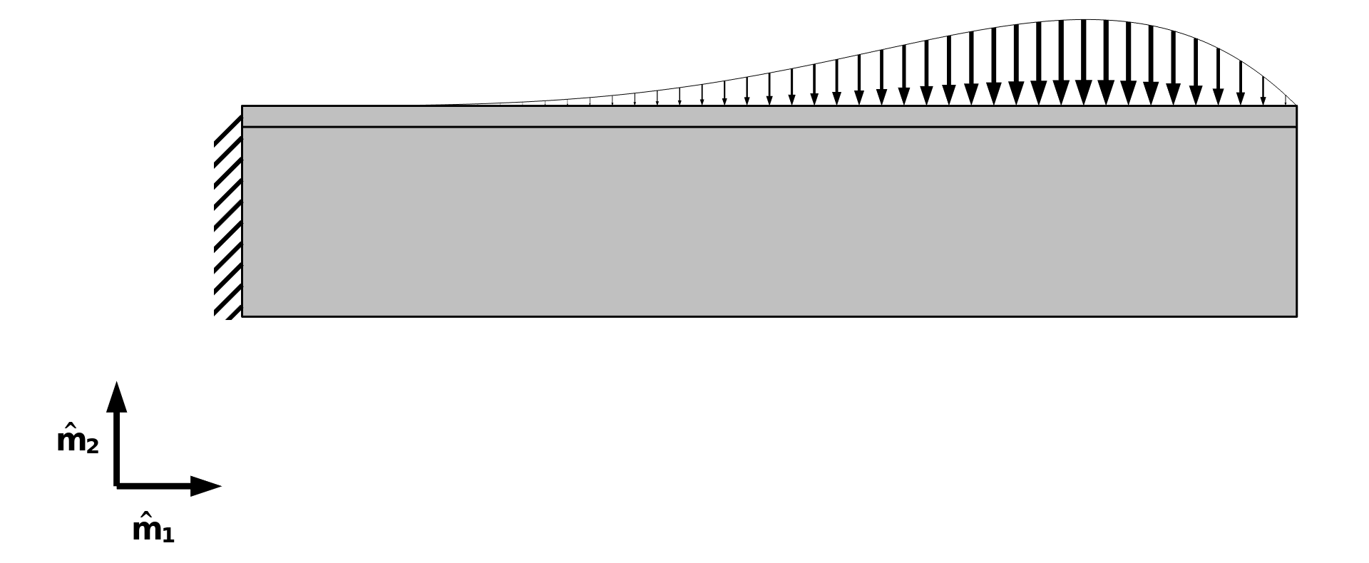
Figure 2. The problem formulation of the Topology Optimization of a Beam with Milling Constraints model, including the milling directions \hat{m}_1 and \hat{m}_2. The left end of the beam is fixed, whereas the top boundary is subjected to a distributed load.
The Density Model feature has settings for milling constraints, as shown below. It’s important to enable projection, and oftentimes it’s also necessary to initialize the control variable field to a value significantly smaller than 1.
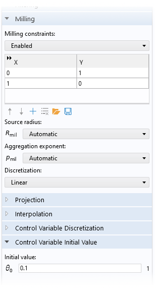
Figure 3. The user interface (UI) of the Density Model feature is shown for an example where milling constraints are enabled. The Projection section is collapsed in the figure, but (for this example) projection is enabled with a default slope and projection point.
The setup of the optimization problem is defined in the Optimization study step. MMA is the recommended optimization solver method, and sometimes it’s beneficial not to use the globally convergent version and/or move limits. The optimization works fine with the default Fully Coupled solver, but the equation system in the previous section consists of a linear equation for the filtering, with a one-way coupling with two linear equations for the convection. There is another one-way coupling from the last equation to the equation systems associated with the Solid Mechanics interface. Therefore, it’s significantly faster to solve using a Segregated solver. In this case, the Segregated solver speeds up the computation by around 2 times.
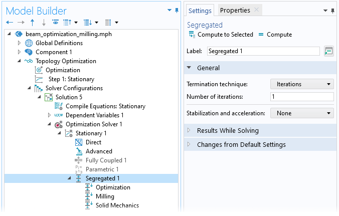
Figure 4. The setup of a Segregated solver for a set linear one-way coupled problem. When using the Solid Mechanics interface to define a linear system, one can even limit the solver to a single iteration to save a bit of computational time. Alternatively, one can use several iterations for the Solid Mechanics interface step.
The result of the optimization is illustrated in the animation below. In 2D, the introduction of milling constraints prevents holes, so in this sense the topology is actually fixed and the method is essentially reduced to a type of shape optimization that allows large deformations. The most relevant uses of milling constraints thus involve modeling in 3D, as we shall see with the next two examples.
The material volume factor, \theta, is plotted for different iteration numbers. The result of topology optimization without milling constraints is shown in Figure 1.
Example 2: 3D Torsion Ball
Milling constraints reduce the amount of design freedom, and by itself this ought to make it easier to find a good optimum, but because nonlinearities are also introduced, one can, in practice, easily end up in bad local minima. This can be (somewhat) avoided if one uses a continuation strategy in the projection slope and SIMP exponent, \beta and p_\mathrm{SIMP}, respectively. This strategy often results in good 3D designs, but the choice of parameters can be sensitive to the problem and the number of milling constraints.
In this example, we will consider a torsion sphere, which is a classic benchmark problem with a torsional load case, as sketched below. The objective is to maximize the stiffness between a fixed box and a box subjected to a torque. The boxes are separated along the axis of the torque, and the design is subjected to a mass constraint (equivalent to a volume constraint).
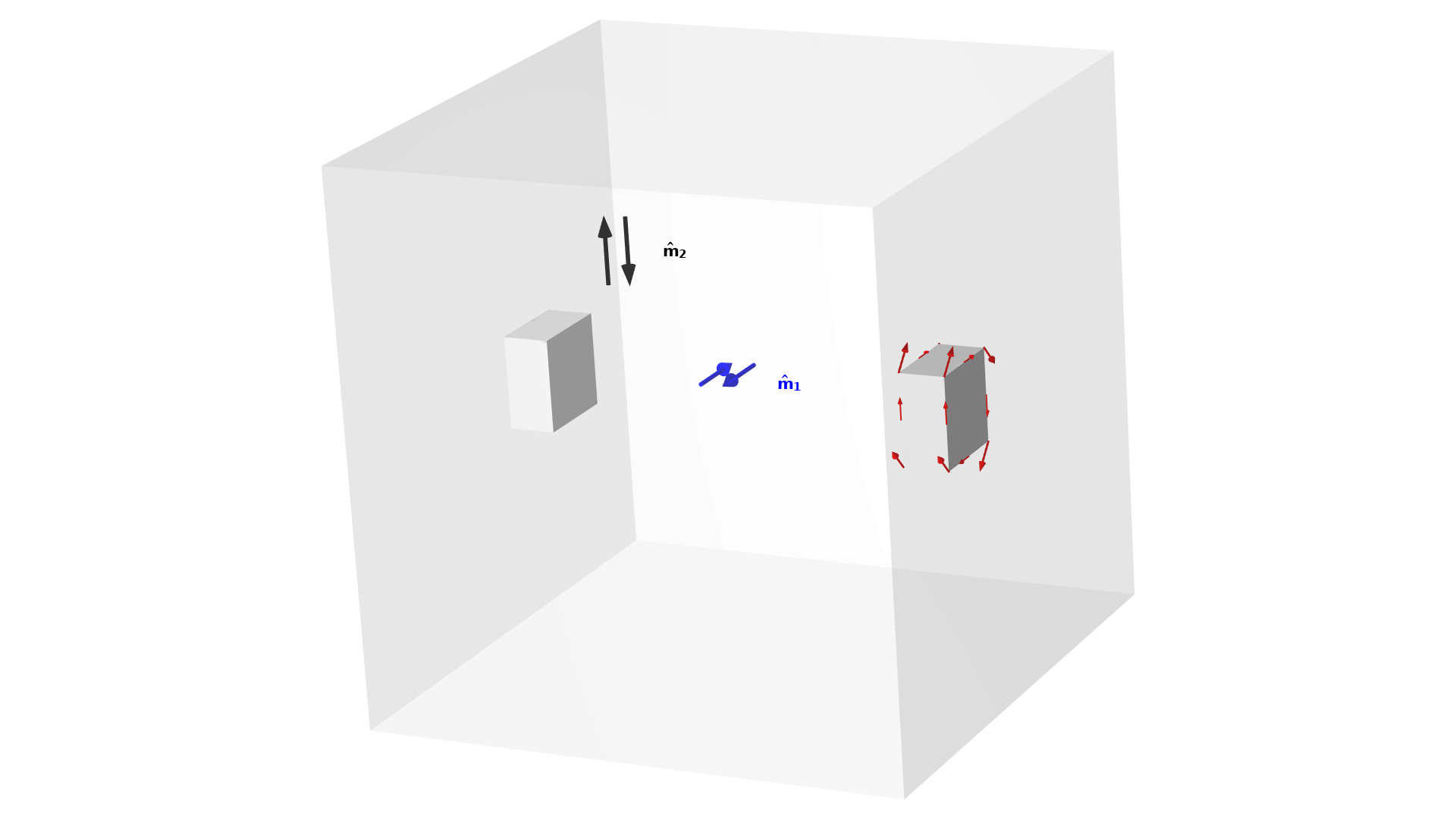
Figure 5. The setup for a torsion ball problem. There are four milling directions, but symmetry is imposed, so only two milling directions have to be considered.
The animations below show the designs resulting from optimization with and without milling constraints. The Density Model feature supports both linear and constant discretization for the convective equation, and this example demonstrates the constant option, which gives a less smooth output.
The elements with 0.5<\theta are plotted in gray for optimization with (right) and without (left) milling constraints. The value of the objective and the continuation parameters are shown for every iteration.
The optimization without milling constraints results in a closed spherical design with an internal cavity. This design is impossible to manufacture with conventional subtractive manufacturing methods, which makes the problem well suited for testing manufacturing constraints. The optimization with milling constraints produces a design without internal cavities, but this comes at the cost of a compliance (inverse stiffness) that is around 40% higher. The topology is sensitive to the details of the continuation scheme, though it’s difficult to improve significantly on the objective without adding more milling directions.
Example 3: Wheel
The final example is a structural 3D problem. The objective is still to maximize the stiffness subjected to a volume constraint, but this example differs from the previous problem in three ways:
- 12 load cases are used instead of 1
- Sector symmetry is imposed on the design only (not the physics)
- Linear discretization is used for the convective equation
The use of 12 load cases causes significantly more computational work. These load cases can, however, be computed in parallel, so the computational time does not have to increase significantly, if the appropriate hardware is available.
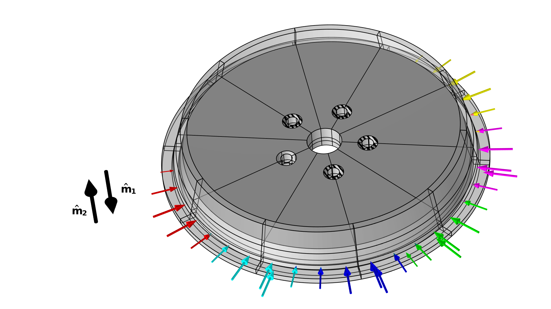
Figure 6. The setup for the wheel problem is illustrated with the load cases shown in various colors and the milling directions shown in black. Note that there is a second set of cases in the axial direction, and that only four of the bolt holes are constrained.
The sector symmetry is imposed using a General Extrusion operator, which maps the design variables from the “control sector” to the other sectors.
The elements with 0.5<\theta are plotted in gray for optimization with (right) and without (left) milling constraints. The value of the objective and the continuation parameters are shown for every iteration.
In this case, the optimization with milling constraints produces a simple topology with nonbranching spokes. The cross section of the spokes has a z-like shape to promote bending stiffness in both directions.
Verification of a Body-Fitted Mesh
The implicit geometry representation associated with the density method always introduces some error. This is due to nonzero void stiffness and because the elements in the transition region between solid and void are associated with a poor stiffness-to-mass ratio. The latter effect usually dominates, and therefore the implicit geometry representation often underestimates the performance. To verify the performance of the design, one can use a Filter dataset to transfer the design to a new component. You can either use a Boolean expression to cut through the elements so that most of the mesh can be recycled, or you can import the design as a new geometry and make a new mesh from scratch, as demonstrated in the figure below. The setup of the new components is simplified by the fact that physics interfaces (and features) support copy-paste functionality. The selections of the physics interfaces are reset, but all selections defined under geometry and definitions are transferred automatically for use in the new component.
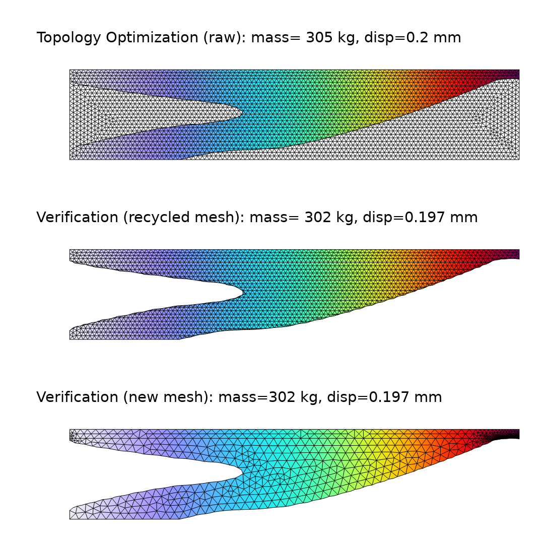
Figure 7. The displacement field and mesh are plotted for the raw topology optimization of the first example (top). Both the approach with (center) and without (bottom) recycling of the mesh are shown. The mass and constraint are plotted for all cases.
Next Step
To learn more about the features and functionality for performing optimization, check out the Optimization Module; click the button below.
References
- L.C. Høghøj and E.A. Träff, “An advection-diffusion based filter for machinable designs in topology optimization,” Computer Methods in Applied Mechanics and Engineering, vol. 391, p. 114488, 2022; https://www.sciencedirect.com/science/article/pii/S0045782521007003


Comments (2)
Salih Kaya
February 18, 2023After defining materials to domains in COMSOL, why does it want materials to boundaries as well?
Kristian Ejlebjærg Jensen
February 20, 2023 COMSOL EmployeeIt sounds like you have a Shell interface. I suggest that you contact comsol.com/support for help.