Computing the spatial derivative of the magnetic field or magnetic flux density is useful in areas such as radiology, magnetophoresis, particle accelerators, and geophysics. One of the most important use cases is the design of magnetic resonance imaging (MRI) machines, where it is necessary to analyze not only the field strength but also the spatial variation of the field. Today’s blog post demonstrates how to compute and plot the gradients of the magnetic field in electromagnetic simulations in the COMSOL Multiphysics® software.
Editor’s note: This blog post was updated on 11/24/2020 to reflect new functionality and information.
Spatial Derivatives: Background and Objective
When you are computing magnetic fields induced by currents, computing electric fields induced by time-varying magnetic fields, or solving 3D electromagnetic wave problems, COMSOL Multiphysics uses so-called curl (vector or Nédélec edge) elements in all three cases. The curl element is also used in 2D and 2D axisymmetric magnetic field simulations that involve in-plane current distributions. Within the AC/DC Module, the curl element is typically used to compute the magnetic vector potential, A. However, the higher-order spatial derivatives are not available for the curl element.
Check out the blog post What Is the Curl Element (and Why Is It Used)? for an elaborate introduction to the curl element.
The magnetic flux density B, magnetic vector potential A, and magnetic field H are related through the magnetic permeability μ, as given by the following:
The equations show that the magnetic flux density and the magnetic field are functions of the first-order spatial derivative of the magnetic vector potential. Since the second-order spatial derivative is not defined on curl elements, the gradients of B and H cannot be derived by using the differentiation operator (d(f,x)) directly.
In order to compute the second-order spatial derivative, the B or H field defined on curl elements is usually mapped to a field represented by Lagrange elements. Thanks to the operator laginterp(order, expr) introduced in COMSOL Multiphysics version 5.6, it is more convenient to do this. The operator maps an expression to a Lagrange field of a specified order and then evaluates on that field in each mesh element.
When solving for 2D or 2D-axisymmetric magnetic field problems involving out-of-plane currents, or static magnetic field problems without any current flow within the model, the Lagrange elements are used to solve the governing equations, which makes the second-order spatial derivative available. The method shown in this blog post applies only to cases where the curl elements are used to compute the fields.
When solving the magnetic field with the Magnetic Fields, Currents Only interface (available as of version 5.6), which uses the Lagrange element as the shape function for the dependent variable, the
d(f,x)operator can be used directly.
An Example: Helmholtz Coil
Let’s look at an example where we can demonstrate the usage of differentiation operator introduced above. We will show how you can compute and plot the spatial derivatives of the magnetic flux density produced by a Helmholtz coil. A detailed description of this model, along with step-by-step instructions to simulate the coil, can be found in the Application Gallery.
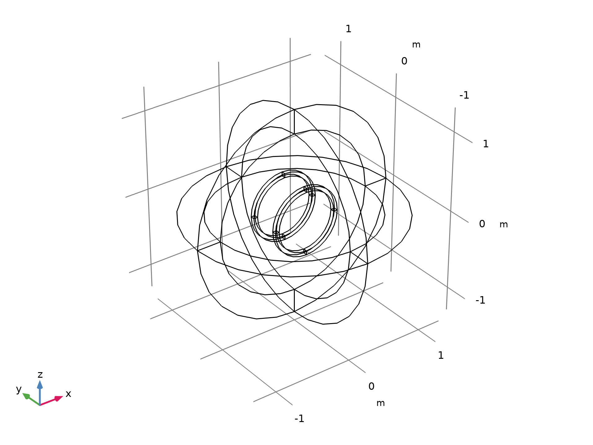
A Helmholtz coil is a pair of parallel circular coils separated by a distance equal to one coil radius where the current through both the coils flows in the same direction. Some known uses of this kind of configuration are canceling Earth’s magnetic field and generating controlled magnetic fields for experiments. The geometry of the Helmholtz coil is shown in the figure below. In this model, each coil has 10 turns and a 0.25-mA current circulating through it.

The geometry of the Helmholtz coil. The outermost sphere region is modeled with the Infinite Element.
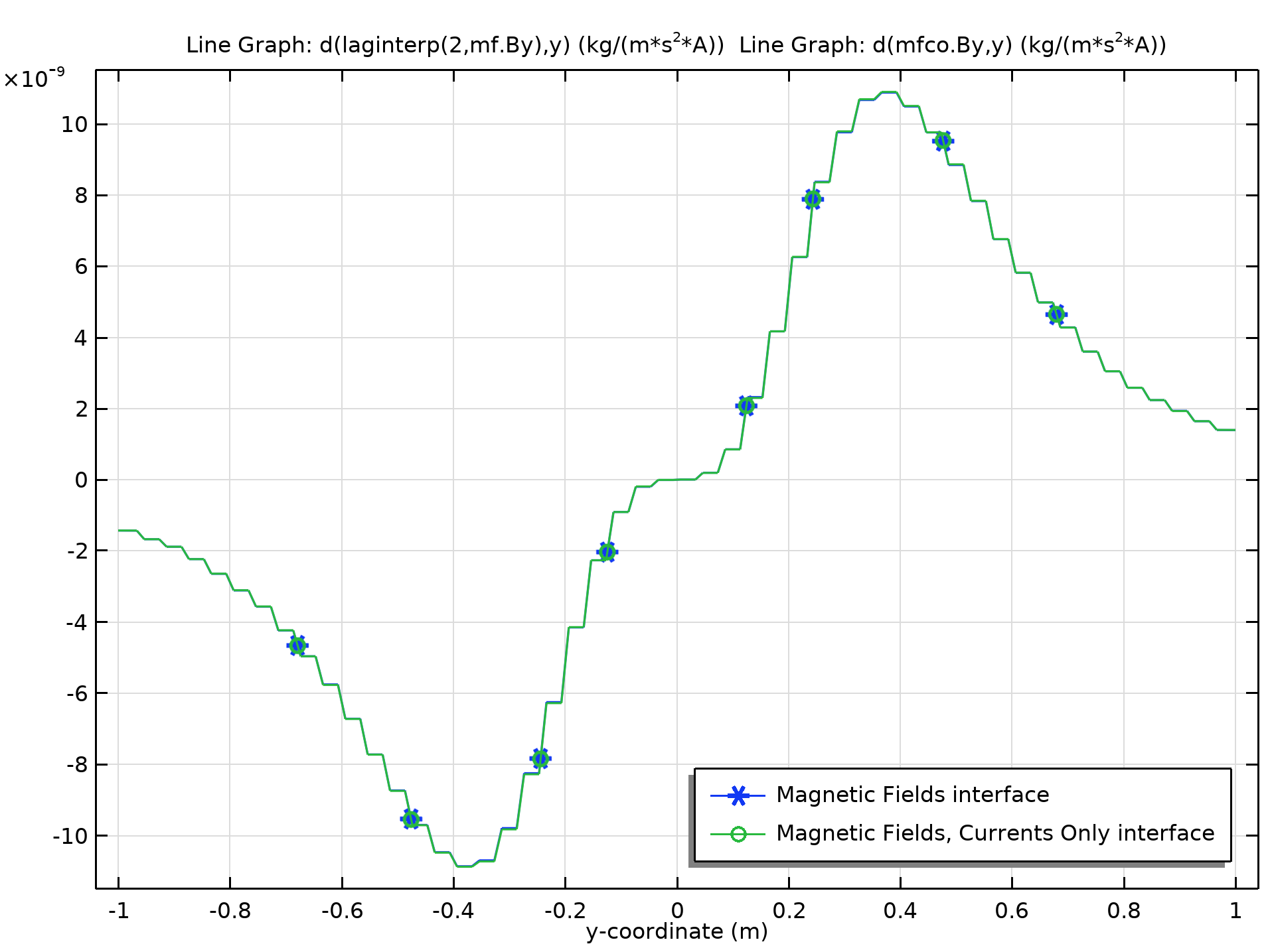
This model demonstrates two different approaches to compute the magnetic flux density and its spatial derivative. The first approach uses the Magnetic Fields physics interface and the Coil feature to model the two coils. The Magnetic Fields interface uses the curl element to define and represent the magnetic flux density in 3D. For example, to compute the gradient of the y-component of the magnetic flux density (Byy), we use the expression d(laginterp(2,mf.By),y).
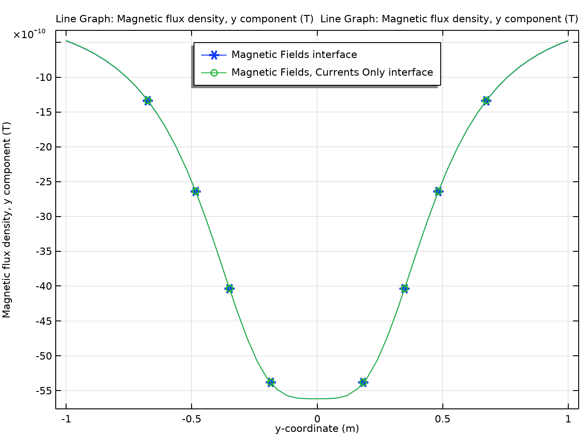
The second approach uses the Magnetic Fields, Currents Only physics interface, as there are no magnetic materials in the model. The coils are modeled with the Conductor feature. Since this interface uses the Lagrange shape function, we can use the expression d(mfco.By,y) to compute Byy. The comparisons of By and Byy along the centerline of the Helmholtz coil are shown in the figures below. As can be seen, the value of Byy in each mesh element is constant, since both of the interfaces use quadratic elements for the magnetic vector potential A.

The y-component of the magnetic flux density along the centerline of the Helmholtz coil.

The gradient (with respect to the y direction) of the y-component of the magnetic flux density along the centerline of the Helmholtz coil.
Next Steps
Download the Magnetic Field of a Helmholtz Coil model by clicking the button below, which will take you to the Application Gallery.
Learn more about the features and functionality of COMSOL Multiphysics and the add-on AC/DC Module:


Comments (7)
Jiawei Tian
September 24, 2021Thanks for providing this valuable information.
I have a question about using PDE to map the B from curl element to Lagrange element. The PDE is a coefficient form PDE. However, I am confused to set the value of the coefficient. I tried to set c=1 and f=1 to make the form be possion’s equation. By doing this, I got the value of u1,u2,u3, which are corresponding to Bx, By, Bz. Afterwards, I make a comparison between norm.B and sqrt(u1^2+u2^2+u3^3). The result is same. So my question here is why I can use the possion’s equation to map B from curl element to u in Lagrange element. I confused about the reason for solving this pde to get u. Thanks.
Lipeng Liu
September 24, 2021 COMSOL EmployeeHi Jiawei,
Thank you for your comment. I cannot provide support here without seeing your model.
Please contact our Support team.
Online Support Center: https://www.comsol.com/support
Email: support@comsol.com
Jiawei Tian
September 25, 2021Thanks for your quick reply. I created a support case (4908032). The COMSOL model is also attached there. The link is pasted below:
https://www.comsol.com/support/case/4908032/
Looking forward to seeing your response. Thanks.
Samuel Packman
March 15, 2023Thanks for making this post. One question I have is whether there are any guarantees that the weak solution to the PDE that COMSOL calculates will have the same derivatives as the actual strong solution to Maxwell’s equations. The use of the interpolation function for mf.B assumes that there are no small scale variations in the true magnetic field, so is there any theoretical justification for that? Thanks.
Lipeng Liu
March 16, 2023 COMSOL EmployeeHi Samuel,
The interpolation method used here is essentially the same as the mapping method (from low to high order mesh element). Therefore, its error estimates are the same as the classical error estimates you find in FEM textbooks. In general, weak solutions approach exact solutions when you refine the mesh or use higher order discretization.
Regards,
Lipeng
煌煌 金
March 29, 2023Thanks for making this post.
However, COMSOL version on my computer is 5.5, which is about to update in near future. Right now, I need to plot Spatial Derivatives of static magnetic field without any current flow within the model.
So, I need to refer to your post before update. Thanks.
Lipeng Liu
March 30, 2023 COMSOL EmployeeHi 煌煌,
Please contact our Support team.
Online Support Center: https://www.comsol.com/support
Email: support@comsol.com