I’ve written several blog entries involving permanent magnets, in one way or another. Reading those may have raised the question “what about a more simple introduction to permanent magnet simulations?” Fair enough, here’s how to model a permanent magnet and its surrounding magnetic field.

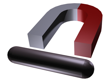
Horseshoe permanent magnet and an iron rod.
About Magnetostatics
Before we dive into the permanent magnet modeling, let’s quickly go over the general concept of magnetostatics. Simply put, magnetostatics involves studying magnetic fields in systems where the magnetic currents do not change with respect to time (they’re steady). This is contrary to the eddy current brakes we discussed a while back, where the magnetic field does change with time. The particular permanent magnet model we will go through today turns out to be a great example of a magnetostatic problem.
Setting up the Permanent Magnet Model
Let’s suppose we want to model the magnetic field that surrounds a horseshoe permanent magnet. In accordance with the image at the top of this post, we also want to have a look at how the magnet interacts with a metal rod. When modeling the magnetic field and computing the force that acts on the rod, we can take advantage of the geometry’s symmetry and the magnetic field’s antisymmetry. Although this isn’t a computation-heavy problem, it is a good example for introducing the concept of symmetry. Knowing when to take advantage of symmetry can save you a lot of time, and in the case of our simple magnet example, only a quarter of the geometry then needs to be modeled. As an advocate for efficiency, I’d say that’s very nice, indeed.
Using COMSOL Multiphysics along with the AC/DC Module, we can get started with defining the magnetic scalar potential, Vm, by selecting the Magnetic Fields, No Currents interface. Doing so prompts the model to use the appropriate equation: –∇ ⋅ (μ0∇Vm – μ0M0) = 0.
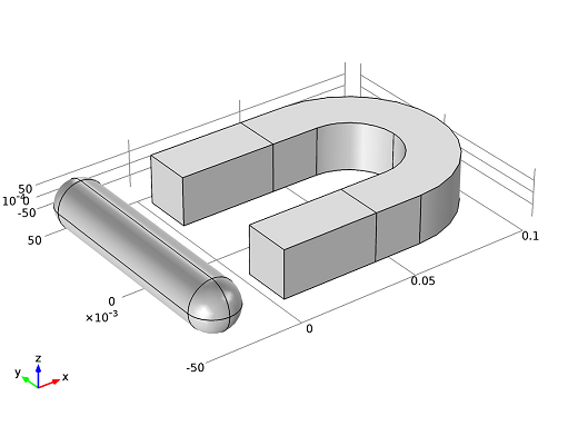
Next, we want to import the permanent magnet geometry from the Model Library. The geometry includes both the horseshoe magnet and the metal rod, but as you can see, it shows the components in their entirety:

I mentioned we could take advantage of our problem’s symmetry and antisymmetry to speed up our simulations, and now is the time to do so. We can use the xy– and xz-planes to form our geometry’s exterior boundaries, as they correspond with the magnetic field’s symmetry and antisymmetry, respectively. To do that, we will need to create an air box, and then delete the parts of the geometry we no longer want to work with (complete instructions on how to perform this and all other steps can be found in the permanent magnet’s model documentation).
The magnetic field is tangential to the boundary on the xy-plane, and perpendicular to the boundary on the xz-plane, which is described by the Magnetic Insulation and Zero Magnetic Scalar Potential conditions, respectively.
Modeling the Magnetic Field and Calculating the Force on the Metal Rod
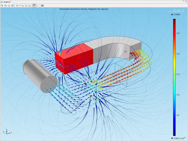
If we plot the magnetic flux density, we can visualize the magnetic field that surrounds our permanent magnet. By also adding an arrow plot, we can view the direction of the field.

Finally, we can compute the force the permanent magnet exerts on the rod, by using a Global Evaluation. Upon doing that, we learn that the magnet exerts a force of 1.53 N on the metal rod. Remember, we only modeled a quarter of our geometry, so the actual force on the rod is therefore four times this value, or 6.11 N.


Comments (7)
Charve Lau
April 24, 2014Hi, Fanny Littmarck. Thanks for sharing. I am a beginner on Comsol, and I have build a first comsol model on permanent magnet referencing ‘The Magnetic Field from a Permanent Magnet’ . My interest is to check the magnetic density of the magnetic circuit I built with a permanent magnet and several pole pieces. However, the magnetic field is restricted in the permanent domain I have defined. Can you help figure it out? I really appreciate it. Cause I cannot post image or file here, may I post a post in the community or I send you an email? My email is lqwei7@sjtu.edu.cn
Thanks!!!
Fanny Griesmer
April 30, 2014 COMSOL EmployeeHi Charve,
Happy to hear you are using COMSOL Multiphysics. For help with your specific case, please send your file and question(s) to support@comsol.com.
Amit Sharma
March 31, 2017Will size of air box have an effect on force on iron as simulated in this model?
Caty Fairclough
April 13, 2017Hi Amit,
Thank you for your comment.
For questions related to your modeling, please contact our support team.
Online support center: https://www.comsol.com/support
Email: support@comsol.com
Best,
Caty
Lincoln Frost
May 4, 2017Would it be fair to assume that a second force calculation node could be added, to compute the force on the magnet? And that this should be equal and opposite to the force on the rod?
Caty Fairclough
May 15, 2017Hi Lincoln,
Thanks for your comment.
Yes, that would be correct.
Mayank Srivastava
October 9, 2021If speaking specifically for my case, where there r two magnets kept above and below the workpiece (say any para or diamagnetic material), what will be the specific governing equation we will be using?
I want to observe the variation of magnetic flux density over the w/p by varying the magnet distance from the workpiece….
Also, what are the boundary conditions needed to simulate the current scenario??