Ships and submarines can be detected by enemy defense systems due to their magnetic signatures. Therefore, numerical analysis of the magnetic signature is of great importance in the design and operation of such vessels. However, the sheet metal used for construction is thin compared to the dimensions of the vessel, which makes the standard finite element approach with volume meshing inefficient. This blog post discusses a way to speed up the computation using a simple submarine example.
The original version of this post was written by Mark Fowler and published on February 24, 2014. It has since been revised with additional details and updated software features.
Detecting the Magnetic Signature of a Vessel
As a vessel travels under or on the surface of water, it causes a detectable local disturbance in Earth’s magnetic field. This disturbance, referred to as the magnetic signature, makes the vessel vulnerable to enemy defense systems. In submarine warfare, adversaries use increasingly sophisticated magnetic sensor and signal processing equipment to detect and track these signatures.

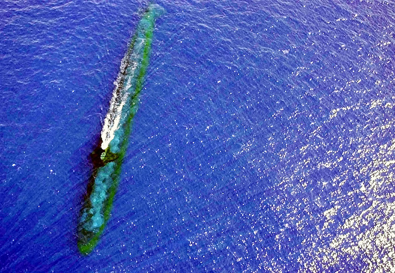
The USS Chicago submarine. U.S. Navy Photo by Photographer’s Mate 1st Class Kevin H. Tierney and in the public domain via Wikimedia Commons.
In order to prevent detection, engineers use degaussing techniques; i.e., methods to suppress the ship’s signature to safe levels. One such technique involves dragging cables that carry strong currents along the ship every now and then, which gives the hull a slight magnetic bias. Other techniques use coils incorporated in the ship’s design, generating a counteracting magnetic field with the appropriate strength and direction to compensate for the disturbance. In order to effectively use these methods, one must be able to analyze the signature based on a ship’s design and magnetic properties.
Analyzing a Submarine with Electromagnetics Simulation
This example focuses on investigating the magnetic signature caused by the strong contrast in permeability between a submarine’s steel hull and its environment (remanence or hysteresis effects are not considered here).
Submarines are essentially long steel tubes. Although the ship hull is built to withstand enormous pressure, it is still relatively thin compared to the size of the vessel. Simulation of such a structure would be computationally demanding using standard finite element analysis because volume meshes of thin, long structures tend to contain either a very large number of elements or elements with a large aspect ratio. This results in a lot of degrees of freedom (high memory requirements) or a mesh that has issues resolving the geometry and the resulting fields.
The submarine is modeled with the Magnetic Fields, No Currents interface in the AC/DC Module, an add-on to the COMSOL Multiphysics® software. Using the Magnetic Shielding feature, you can avoid the abovementioned issues by modeling the thin metal sheets as 2D faces embedded in a 3D geometry. In effect, this feature applies a 2D tangential projection of the 3D domain equations valid in the sheet, where the thickness and permeability of the hull are introduced as parameters. The result is a boundary feature with zero thickness in the geometry and mesh, yet an accurate thickness when considering the involved physics. Similar features are available in the Electric Currents and Electrostatics interfaces to model thin sheets with high conductivity and high permittivity, respectively.
For more modeling details, you can view the step-by-step documentation for the Magnetic Signature of a Submarine example. If you have a valid software license, you can also download the related MPH file.

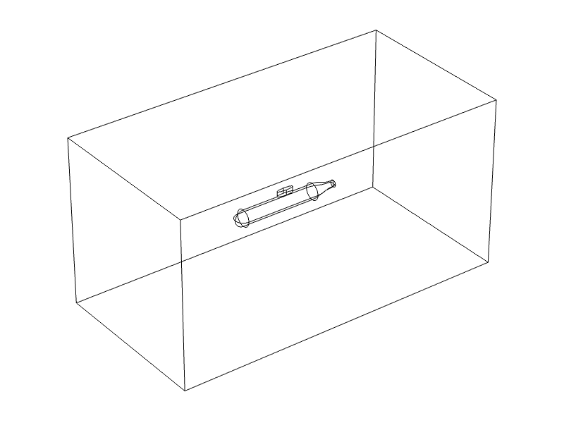
A model geometry of a submarine where face objects represent the submarine and a 3D box represents the surrounding water.
Evaluating the Magnetic Signature of a Submarine
Once you have built the geometry of the submarine and you have retrieved its material properties, you can work toward predicting its magnetic signature. The AC/DC Module contains the Reduced Field formulation, which is a very helpful feature for obtaining the signature. The feature allows you to define the background field as a predefined quantity and solve only for disturbances in the field.

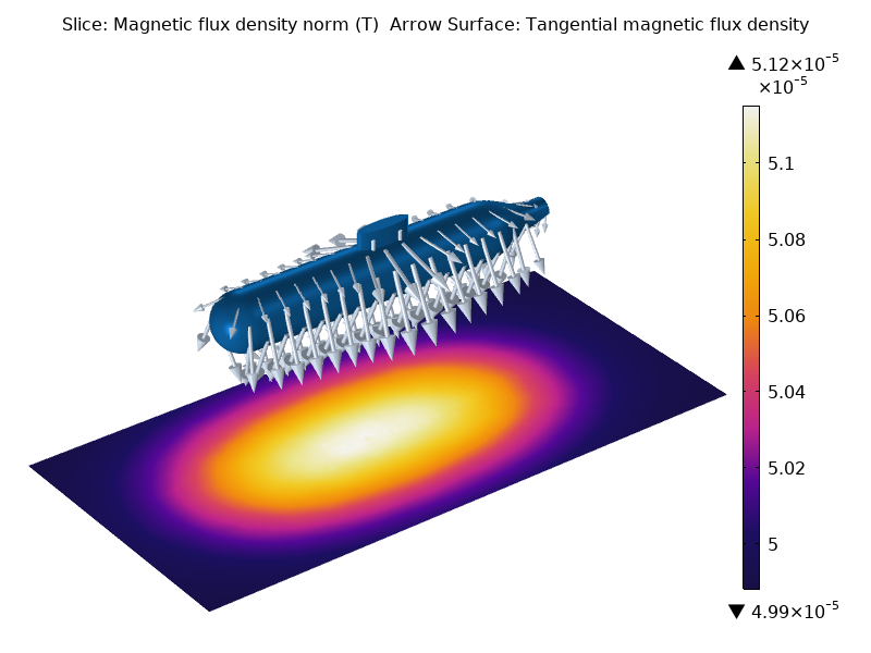
The total magnetic flux density in a horizontal slice plot 12.5 m below the keel. The background of Earth’s magnetic field is set to 5×10⁻⁵ T.
A distinct field disturbance appears due to the presence of the submarine. Shown, using arrows, are the magnitude and direction of the tangential magnetic field in the submarine’s hull.
Next Steps
Try the Magnetic Signature of a Submarine tutorial model yourself by clicking the button below, which will take you to the Application Gallery.
You may also like this blog post on avoiding ship hull corrosion with impressed current cathodic protection and simulation.


Comments (0)