Today, guest blogger and Certified Consultant Mark Yeoman of Continuum Blue shares a numerical modeling example for RFID applications.
We’ll look at how we can make use of COMSOL Multiphysics® simulation software to determine the operating read range of a passive RFID tag powered by a reader’s interrogating field. Additionally, we will look at how we can maximize this operating range by optimizing the tag’s antenna design.
About the RFID Application
Radio-frequency identification (RFID) involves the wireless use of radio-frequency electromagnetic fields to transfer information and identify and track objects with the use of an RFID transponder, or tag, attached to the object in question. These tags are now frequently seen in everyday products, produce, payment cards, and even livestock.
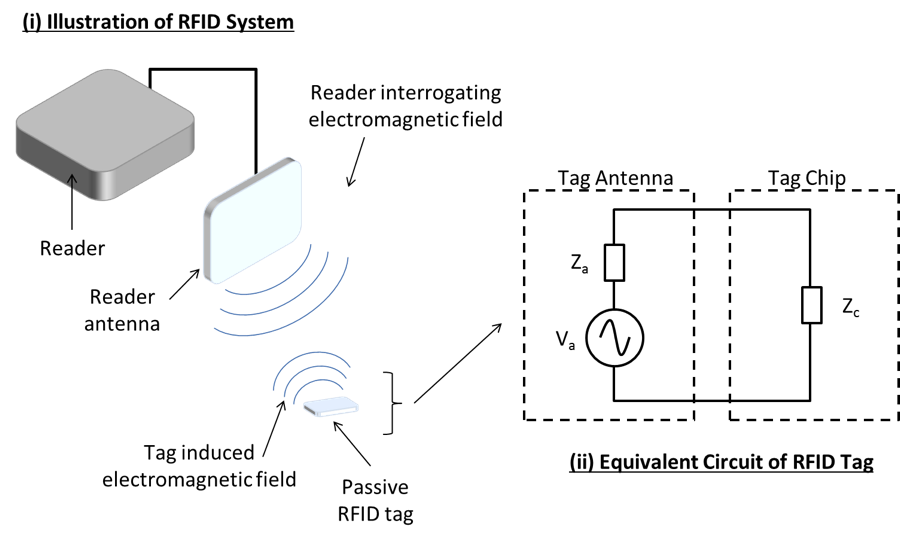
A reader is used to interrogate the tag through electromagnetic fields as illustrated in figure (i) below and information is transmitted back from the tag. With their ever increase in use, there is a rising need to reduce their energy requirements and the size of the tags, while maintaining or maximizing the read range, i.e., the distance at which the tag can be detected.

Illustration of (i) RFID system and (ii) equivalent circuit of RFID tag.
Requirements to Maximize RFID Tag Read Range
RFID tags essentially consist of an antenna and a chip that have complex input impedances as illustrated in figure (ii) above. The chips are typically located at the terminals of the antenna and the voltage (Va), developed at the antenna terminals from the reader’s interrogating field, powers the chip.
In order to maximize the tag’s read range, one simply needs to ideally match the impedance of the RFID tag antenna to the chip utilized in the tag (references listed in the “Further Reading” section) and ensure that for a particular reader, a minimum threshold power (Pth) is achieved at this distance to activate the chip at the required operating frequencies.
Theory and Equations
Fortunately, I’m not going to go into all the theory here. (If you’d like the full details, check out my paper “Impedance Matching of Tag Antenna to Maximise RFID Read Ranges & Optimising a Tag Antenna Design for a Particular Application”, to be released soon via the COMSOL Conference 2014 resource.) However, one can obtain an equation for the Power Transmission Coefficient, τ, which describes the impedance match. Here, as τ tends to unity, the better the impedance match between the chip and antenna, as follows:
(1)
Here, Rc and Ra are chip and antenna resistance, respectively. Zc and Za are chip and antenna impedance, respectively. Additionally, by making use of the Friis free-space equation, we can also obtain an equation for read range, r:
(2)
Here, λ is the wavelength, Pr is the power transmitted by the reader, Gr is the reader antenna gain, Ga is the gain of the receiving tag antenna, and Pth is the minimum threshold power. The peak read range, r, across a frequency range can be referred to as the tag’s resonance and will coincide with the maximum power transmission coefficient, τ.
Numerical Model
With COMSOL Multiphysics® and the RF Module, one is able to develop an analysis model for the RFID tag, including substrate, antenna and chip geometry, and material properties. In addition, we can input the reader system details such as power transmitted, Pr; the reader antenna gain, Gr; and operating frequency.
In our numerical model, we’re able to perform the electromagnetic field and frequency domain analysis of the combined chip and antenna design to determine the antenna’s complex impedance, Za; gain, Ga; the power transmission coefficient, τ; and the read range, r, for a combined reader and tag system.
Furthermore, with the use of the Optimization Module, one can optimize the antenna’s geometric design to maximize the read range. The figure below illustrates the basic features of the RFID tag model, including air domain, perfectly matched layer (PML) regions, tag substrate, and antenna and chip geometries.

COMSOL Multiphysics® model of an RFID tag, including substrate, antenna, and chip.
Model Validation
In order to have confidence in the analysis results from any numerical model, it is important to validate the model. This can be a very costly and time-consuming exercise. Due to budget and time constraints, we’ll compare COMSOL Multiphysics numerical results to physical test data obtained from literature.
In this case, we’ll make use of physical test data presented by Rao et al. (2005), which provides enough physical test data, including read range, r, and power transmission coefficients, τ, at various frequencies for validation purposes. It should be noted that Rao et al. only provided a single chip impedance value for the frequency range. In addition, the geometric and material details of the antenna and tag design were extracted from available images and text.
We set up and ran a frequency sweep of the equivalent tag. Then, we compared the results of the read range and power transmission coefficient with the physical test data provided by Rao et al. and illustrated our findings graphically, as such:

Comparisons of (i) read range and (ii) power transmission coefficient obtained from model vs. physical test data from Rao et al.
As you can see in the figure above, the model trends observed follow those of the physical data, but the COMSOL Multiphysics model peaks are found to be at slightly higher frequencies than those presented by Rao et al. As expected, there will be a slight difference between the numerical and physical test data due to the limited chip impedance and material data provided in the literature. Moreover, small errors in the extraction of the antenna geometric dimensions may have occurred.
We did, however, consider the small percentage deviations from the physical test data acceptable under these circumstances. We also deemed the modeling method able to correctly predict the observed read range.
Antenna Design and Optimization
Now that we’ve developed a COMSOL Multiphysics model and compared it to physical test data from literature, we’re confident enough to use it to predict the read range of the tag for different chip or antenna designs, in combination with various reader and reader antenna systems. If we’re not completely satisfied with the read range, we can then optimize the design to maximize the read range.
In this example, we’re going to make use of a specific chip, reader, and reader antenna from known suppliers to find the read range of an example tag antenna design. The example design was required to have a maximum 75×45 millimeter footprint area and was based on the “Murata-A3” inlay antenna design for a durable tag. The figure below illustrates the example tag antenna design and compares it to the “Murata-A3” (95×15 mm) antenna.

Example tag antenna design (71.2×15 mm) and comparison to Murata-A3 (95×15 mm) inlay antenna design for a durable tag.
The specific chip, reader, and reader antenna from known suppliers:
- Murata MAGICSTRAP® component (Murata Manufacturing Co., Ltd., Japan)
- Chip frequency: 866.5 MHz
- OBID i-scan® LRU1002 UHF Long Range Reader (FEIG Electronic GmbH, Germany)
- Reader Power: 1W (mid-range value)
- OBID i-scan® UHF Reader Antenna (FEIG Electronic GmbH, Germany)
- Reader Antenna: ID ISC.ANT.U.270/270
- Reader Antenna Gain: 9 dBi
- Chip Impedance: 15-45 j ω
- Tag Substrate Material: FR4 (250 mm thick)
When running this model, we obtained 0.303 and 1.59 meters for the power transmission coefficient, τ, and the read range, respectively. The read range was deemed a little low compared to the required 2 meters for the application at hand. That’s when we turned to the Optimization Module to find an optimal antenna design that would give a read range greater than 2 meters.
In order to get the maximum read range, one can simplify the analysis work and optimize for the maximum power transmission coefficient, τ, for the tag design and then determine the read range based on Equation (2) in combination with the reader system. The geometric variables involved in the antenna optimization process included 34 length and width parameters as illustrated below.

Schematic illustrating the tag antenna design and geometric variables on one side only.
In addition to the constraint of keeping the antenna design within a 75×45 mm footprint area, manufacturing tolerance constraints obtained from a subcontractor were implemented, as well as some constraint on the possible lengths and widths.
Optimization Solvers
We looked at two gradient-free optimization methods in the work; namely, the bound optimization by quadratic approximation (BOBYQA) method and the Monte Carlo method. These were chosen because the objective function does not need to be differentiable with respect to the control variables, and the definition of the problem and the geometric relations and constraints will be discontinuous, making traditional hill climbing optimization methods unsuitable.
Optimized Solution and Results
Overall, it took a total of 42 hours and 23 minutes of simulation runtime to find the optimized antenna design, using both the BOBYQA and the Monte Carlo methods in series, with the use of a PC with two E5649 (2.53 GHz) Xeon® processors and 32 GB RAM.
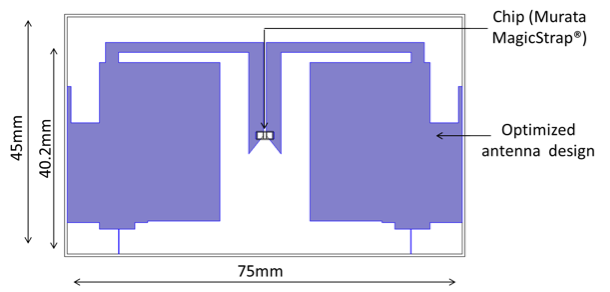
The final objective value found was 0.675, a vast improvement on the initial 0.303. This gave a read range of 2.38 meters when used in combination with the OBID i-scan® LRU1002 UHF Long Range Reader and the OBID i-scan® UHF Reader Antenna, 0.38 meters greater than our minimum requirement of 2 meters.
The geometric characteristics of the optimized tag antenna design are detailed in the figure below. As you may see, this optimized antenna design is vastly different from the initial design, where the final solution fills a large percentage of the space available and has a dramatically different design scheme.

Optimized RFID tag antenna design.
In addition to this, by changing the reader power settings and the type of reader antenna used, one can also assess different reader system specifications. So, for example, by boosting the reader to 2 W and using the larger 600/270 OBID i-scan® UHF Reader Antenna, the read range can be increased to 4.23 meters.
Regional Tag Response Requirements
With this optimized design, one can also assess the tag’s response across a frequency range for various regional requirements. For example, the Industrial, Scientific and Medical (ISM) Radio Band requirements for Europe are 865-868 MHz, while those of the USA are 902-928 MHz.
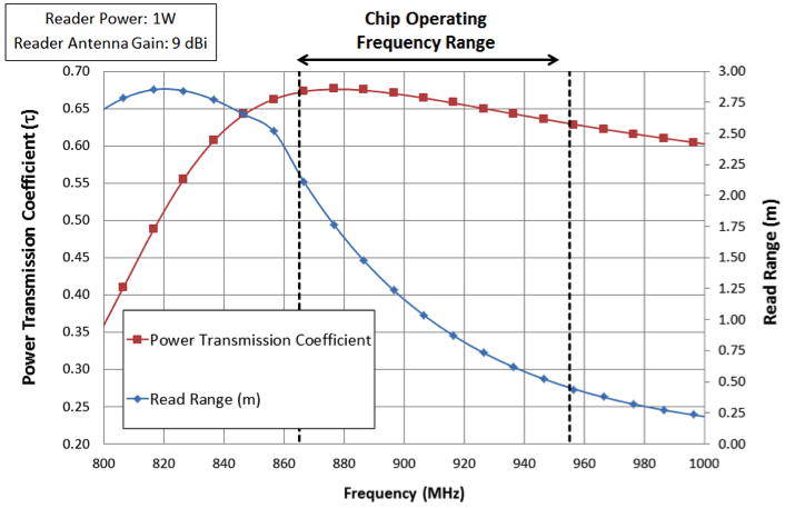
So, how will the same tag design respond in the USA? We can easily test this in our COMSOL Multiphysics model. The results of power transmission coefficient, τ, and read range, r, are presented graphically in the figure below for the tag design from 800 Hz to 1000 Hz.

Frequency response of optimized antenna design.
As we can see from the figure, for the USA, the tag’s minimum read range is 0.73 meters at 928 MHz. Thus, we know that this design is not going to fare well in the U.S. and we need to look at optimizing the design for the U.S. as well as for the European market
In the end, we find that COMSOL Multiphysics software can not only help us find the read range of a passive RFID tag design, but it can also assist in the design of better antennas, which ideally match the chip and maximize read range for specific requirements and regions worldwide.
Further Reading
- Hsieh et al., Key Factors Affecting the Performance of RFID Tag Antennas, Current Trends and Challenges in RFID, Chapter 8, 151-170, Prof. Cornel Turcu (Ed.), InTech (2011).
- N. D. Reynolds, “Long Range Ultra-High Frequency (UHF) Radio-frequency Identification (RFID) Antenna Design“, MSc Thesis, Purdue University (2005).
- Serkan Basat et al., “Design and Modeling of Embedded 13.56 MHz RFID Antennas“, Antennas and Propagation Society International Symposium, IEEE (2005).
- Rao et al., “Impedance Matching Concepts in RFID Transponder Design“, Fourth IEEE Workshop on Automatic Identification Advanced Technologies (2005)
- Yeoman et al. “The Use of Finite Element Methods & Genetic Algorithms in Search of an Optimal Fabric Reinforced Porous Graft System“, Annals of Biomedical Engineering, 37 (2009).
About the Guest Author

OBID i-scan is a registered trademark of FEIG ELECTRONIC GmbH.
MAGICSTRAP is a registered trademark of Murata Manufacturing Co., Ltd.


Comments (0)