
In COMSOL Multiphysics version 5.2, the CFD and Microfluidics modules include a new fluid flow interface for modeling separated three-phase flow. The model behind this fluid flow interface accounts for surface tension between each pair of fluids, contact angles with the walls, as well as the density and viscosity of each of the fluids. The phase field method computes the shape of the interfaces between the three phases and also accounts for interactions with walls.
Modeling Separated Multiphase Flow
COMSOL Multiphysics has offered modeling and simulation capabilities for multiphase flow for many years. However, the equation-based formulation of three-phase flow problems has been used successfully by only a few experts in our user community, as seen in the figure below. In the last two or three years, we have received numerous requests for a more user-friendly, ready-made three-phase flow interface. In COMSOL Multiphysics version 5.2, we have satisfied these requests.
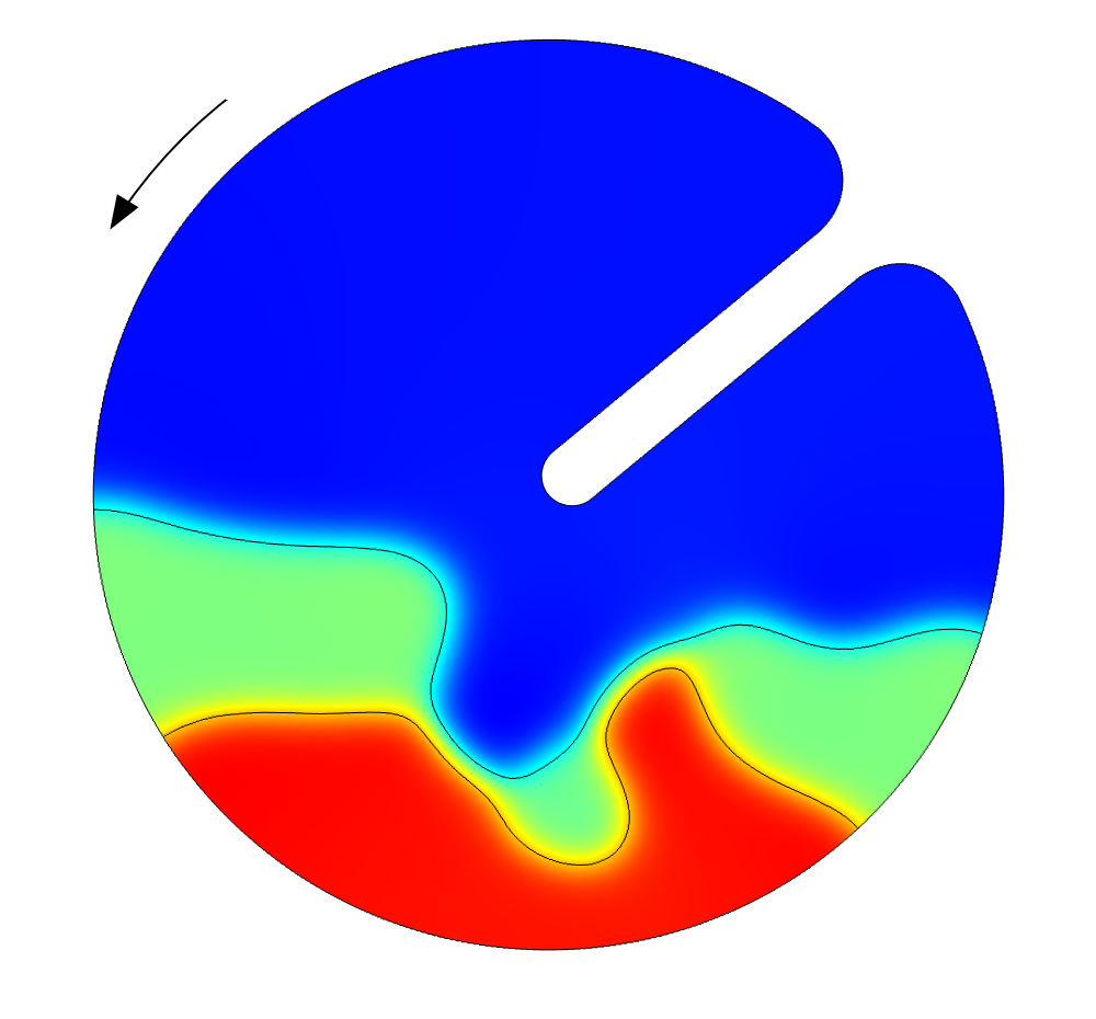
Simulation results of a rotating drum with three-phase flow, performed by a COMSOL Multiphysics user with equation-based modeling.
The description used in this new flow interface, the Three-Phase Flow, Phase Field interface, is a separated multiphase flow model. This interface is similar to the level set and phase field models for the two-phase flow interfaces included in earlier versions of the software. This means that the interface between the three immiscible phases (air, oil, and water, for example) is resolved in detail, including the effects of surface tension and contact angles.
Separated multiphase flow models are used for studying microfluidic systems and for fundamental studies of bubble coalescence and droplet breakup mechanisms. These are processes and phenomena where surface tension, contact angles, and buoyancy effects play a significant role on the shape of the phase boundaries between the different fluids and on the velocity field. Microfluidic devices and processes are typically found in analytical chemistry, biotechnology, medical technology, and nanotechnology. They include inkjets, sensors, separation devices, lab-on-a-chip devices, and microreactors.
High-fidelity separated multiphase flow models are usually too computationally expensive for direct use in macroscopic descriptions, since that may require resolving the surface of thousands or millions of droplets and bubbles. However, the results of detailed fundamental studies on a few bubbles and droplets can be used to develop simplified, less computationally expensive models. These simplified descriptions can usually be included in macroscopic dispersed multiphase flow models, which can describe systems with millions of bubbles and droplets. Macroscopic dispersed multiphase flow models are interesting in the study and design of devices and processes in the pharmaceutical, food, chemical, and household product industries.
The tutorial included in the Application Library, shown in the image below, deals with a droplet of air that rises through a layer of water at the bottom of a container and then into a layer of oil, lighter than water, resting on the water’s surface. As the air bubble moves through the water-oil interface, it carries some water in its wake and into the layer of oil. The water entrained in the bubble’s wake forms a “water tail” behind the bubble in the oil layer. This example is a benchmark from scientific literature, which we used to verify the equations in this fluid flow interface.
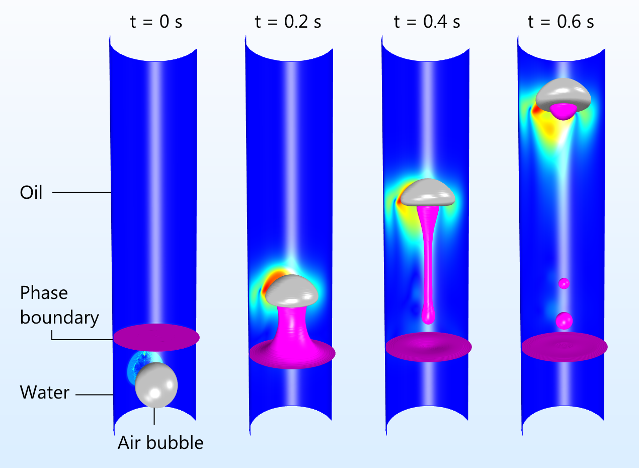
An air bubble penetrates the phase boundary between water and oil and entrains a small amount of water in its wake. The entrained water droplet forms a tail behind the rising bubble.
This problem is interesting in a microfluidic system, since this mechanism can be used to transport small droplets of water into a layer of oil. The water droplets can, for example, be used to extract water soluble species from the oil into the water droplets, while keeping the hydrophobic species in the oil, to perform separation in a very controlled way. If the size of the water droplets is small enough, coalescence of the droplets in the oil phase may be avoided, thus creating droplets with a specific content and weight.
The same model can also be used to calculate the size distribution and coalescence kinetics, which can in turn be used in a dispersed multiphase flow model of an air-water-oil mixture. Emulsions can be used to create powders and structured mixtures.
The Physics and Model Behind the Three-Phase Flow, Phase Field Interface
The schematic below shows the three immiscible phases. The model is based on a free energy formulation of the system using three different phase field variables, with one for each phase (A, B, and C). The phase boundary is determined by the isosurface of a phase field variable for the value of 0.5, which corresponds to the pink and gray isosurfaces in the image above. The sum of all phase field variables in each point in space has to be equal to 1. The phase field variables are thus measures of the content of each phase in every point in space.
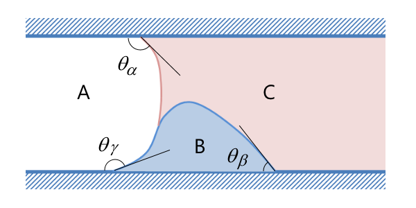
A schematic drawing of the three-phase system, visualized in a projection plane perpendicular to the container walls.
The free energy equation is a function of the phase field variables and the surface tension for each pair of possible boundary interfaces, i.e., AB, AC, and BC. Each of the phase field functions is then used in the conservation equations for each field, which include the minimization of the free energy of the system. The formulated equations are the so-called Cahn-Hilliard equations.
Note also that this formulation accurately treats the triple point between the three phases, which is the point between the blue, pink, and white colored regions for phases A, B, and C shown above. This allows for the simulation of partial and absolute wetting between the three phases.
The interaction with the walls is determined by the contact angles in figure 2, θi, which are set to fixed values. The contact angles are used to express the boundary conditions for each of the phase field variables at the walls. Each angle is computed as the angle between an isosurface of the phase field variable at the value of 0.5, using the projection on a plane perpendicular to the walls, as shown above.
The surface tension forces in the system are also introduced in the equations for the conservation of momentum (Navier-Stokes equations) as sources of momentum. The density and viscosity, at each point in space in the equations for conservation of momentum and mass, are computed from the phase field variables, switching from the values of one fluid to another. Each phase gets the density and viscosity of the pure phase, which smoothly but rapidly changes across the phase boundary at the phase field value of 0.5.
The formulation described above is the one used in the phase field method, which is considered one of the most accurate ways of describing multiphase flow in continuum models.
An Intuitive User Interface
The user interface in the Three-Phase Flow, Phase Field interface in the CFD and Microfluidics modules is a so-called multiphysics interface. This means that, as a user, you have control of both the Cahn-Hilliard equations for the phase fields and the fluid flow equations. Although the settings are available in predefined formulations, an experienced user may also easily extend the equations to include other phenomena; for example, electric fields for studying electrocoalescence.
The image below shows the physics interfaces to the left, in the model tree, which are defined by the Three-Phase Flow, Phase Field interface. The included physics interfaces are the Laminar Flow and Ternary Phase Field interfaces. In addition, the Multiphysics node couples these two physics interfaces in its child node, the Three Phase Flow, Phase Field coupling node.
In the Ternary Phase Field interface, the Mixture node settings contain the input fields for surface tension, as shown below. In addition, the convection term is displayed, showing that the velocity field is obtained from the coupling formulated in the Three Phase Flow, Phase Field coupling node.
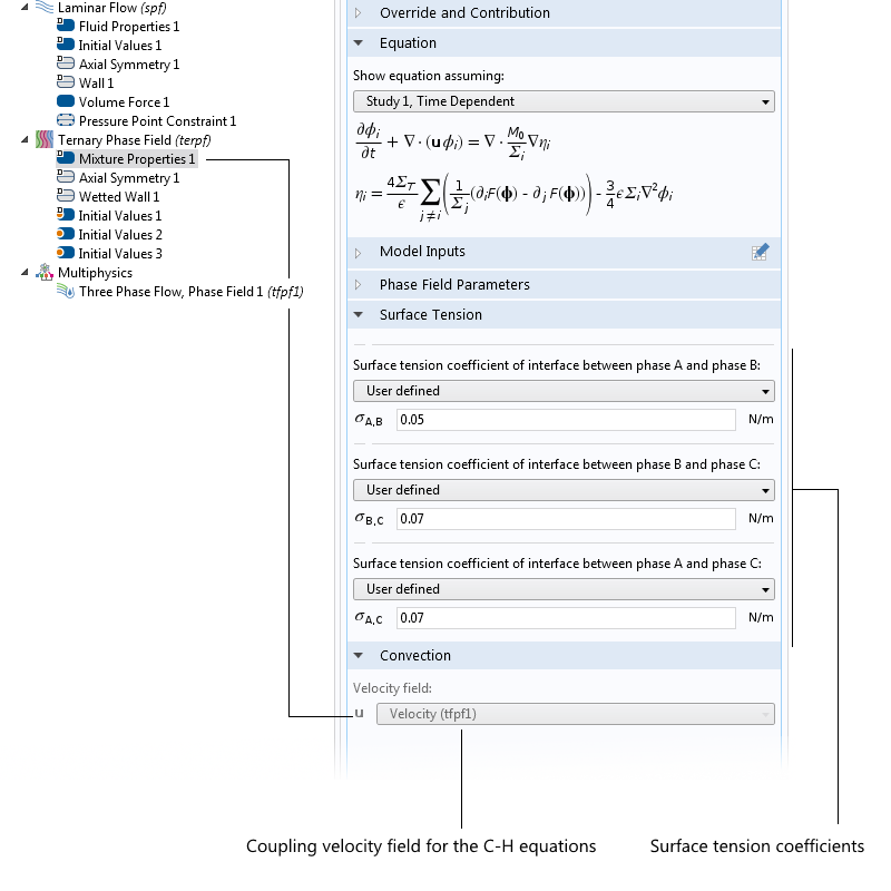
The Mixture node contains the settings for the Cahn-Hilliard equations, which are the surface tension for the mixture and the coupling velocity field. The Equation section shows the domain equations.
The interaction with the container wall is defined by the settings for the Wetted Wall node, shown in the image below. Here, we find the input fields for the contact angles and a description of the notations used for these angles.
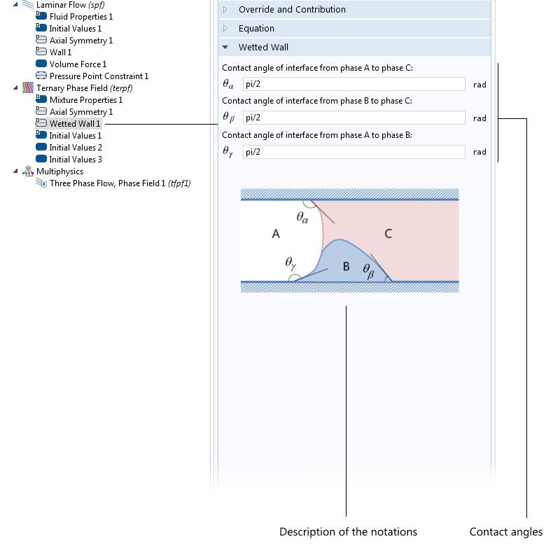
Settings for the Wetted Wall boundary condition, which sets the contact angles for the different phase boundaries with the walls of the container.
The settings for the Three Phase Flow, Phase Field coupling node are shown below. Here, we can see that the coupled physics interfaces are the Laminar Flow and Ternary Phase Field interfaces. For an advanced user, the coupling node gives the possibility to couple the Ternary Phase Field interface to different fluid flow interfaces, which may be defined in different ways or in different domains.
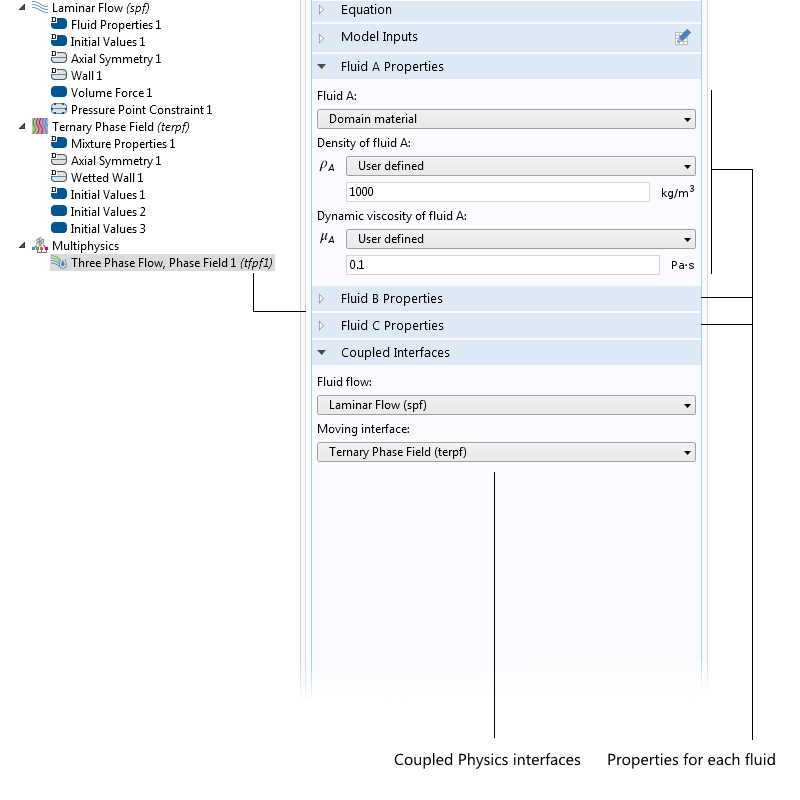
The settings for the Three Phase Flow, Phase Field coupling node.
Possible Future Extensions to the Functionality
The first version of the Three-Phase Flow, Phase Field interface is formulated for laminar flow problems. A natural extension is to also formulate this model for turbulent flow. We are planning to offer this capability in a future release of COMSOL Multiphysics. Another natural addition is to include solid particles in the flow. This can, in fact, already be done using the Particle Tracing for Fluid Flow interface. We also plan to provide related Application Library examples in future software versions.
Further Reading
- Learn about the verification model used in the development of this multiphase flow interface:
- F. Boyer, C. Lapuerta, S. Minjeaud, B. Piar, and M. Quintard, “Cahn-Hilliard/Navier-Stokes Model for the Simulation of Three-Phase Flows”, Transport in Porous Media, 2010, Vol 28, pp 463-483.
- Try simulating multiphase flow on your own with these microfluidic application examples on the COMSOL Blog:


Comments (6)
Nilkamal Barai
March 31, 2016How the three phases and phase boundaries are assigned in the model ? I cant see any such option under “Ternary phase field” . But here i see you have used three initial value nodes (I,2,3), what is the purpose of that? Is it related to assignment of phases in the model ? Please help, and where i can get this tutorial model? It would be helpful if you upload this model if it is not a problem.
Anders Ekerot
April 1, 2016The material properties of the three phases are defined under the Multiphyiscs>Three-Phase Flow node, while the boundary contact angles are defined under the Wetted Wall node.
In addition, three Initial Values nodes are required as each node specifies the initial location for a single phase.
The droplet tutorial model is available for download from the COMSOL Application Gallery: https://www.comsol.com/model/three-phase-flow-bubble-32491
Nilkamal Barai
April 1, 2016Thanks a lot
Kostis Lazaridis
October 19, 2018Hello,
I have a question regarding the Capillary Filling – Phase Field Method (https://www.comsol.com/model/capillary-filling-8212-phase-field-method-1878).
I noticed that when I plot the variable psi (chemical potential) the result is different when I plot the equal quantity of psi which is ” -pf.epsilon_pf^2*(phipfrr + phipfzz + 1/r*phipfr) + phipf*(phipf^2 – 1)”.
Why does that happen?
Unfortunately, I cannot post the pictures for those two different plots here.
Thank you in advance
Kostis
Vikash Kumar
February 2, 2021Hi Andrew
I want to simulate a transient three-phase flow in porous media considering capillary action. The porous zone is initially filled with air. I want to model the displacement of air with two liquid (water and glycerin, let’s say) due to capillary forces. My main interest is the degree of wetting and the spreading of the wetting front. How to model capillary effects in the porous zone?
I did a two-phase simulation, but for the three-phase I need UDFs. I saw your video and found it helpful. Could you please share the momentum source term code for the capillary rise? In addition, how to write UDFs to simulate the three-phase flow in porous media.
Kunal Pardikar
April 16, 2021Hi,
I am interested in your microfluidics module. I was wondering if it can simulate the interactions between two immiscible fluids and their interaction with solid particles. So, I would like to simulate three phases: 2 liquid phases of immiscible fluids and 1 solid phase of particles. Let me know your suggestions of doing this in COMSOL.
Thanks,
-Kunal