
We’ve probably all seen centrifugal force in action in one way or another, whether it be riding on a merry-go-round as a child, spinning a bucket of water upside and observing as the contents hug the insides of the bucket, or watching mud spinning off of a turning tire. In addition to making dizzying carnival rides, this force can be used in the design of many mechanical applications, where it is harnessed to control a variety of effects. One such example is a centrifugal governor (or engine governor), where a centrifugal force is used to regulate fuel supply to an engine.
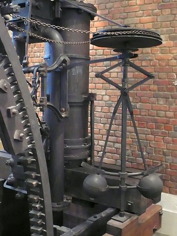
A centrifugal governor in a steam engine from 1788. This steam
engine is currently at the Science Museum in London, England.
Image attribution: Dr Junge.
How Does an Engine Governor Work?
Although the first centrifugal governors date back to 1788 when they were first patented by James Watt, the general principle behind their design has changed very little since then, and they can still be found in modern engines. The first centrifugal governors, like the one pictured above, were used in stream engines where they regulated the speed of the engine by controlling the amount of steam allowed to enter the cylinder. Today, centrifugal governors are most commonly found in internal combustion engines and turbines.
Before we start constructing and analyzing our own model, let’s take a look at the parts of a typical engine governor:

A centrifugal governor, consisting of a spindle, two arms, two links, two flyballs, and a sleeve.
In the diagram shown above, we can see the geometry of a spring loaded centrifugal governor. In this model, the spindle is connected to the output shaft of the engine, which regulates the amount of fuel entering the engine cylinder through the throttle valve. The governor becomes activated when power supplied by the engine’s output shaft causes the spindle to rotate at a certain speed; faster rotations cause more kinetic energy to enter the system. This is where centrifugal force comes into play — as the spindle spins at a faster and faster rate, the rotational motion causes the flyballs to be drawn outwards, which in turn causes the sleeve, links, and arms to rise as well. If the flyballs rise high enough (meaning that a certain threshold of kinetic energy from the engine has been transferred into the system), then the motion of the arms reduces the aperture of a throttle valve. The throttle valve reduces the rate of the fuel entering the cylinder, thus slowing the RPM of the engine. The image below shows the displacement of various parts of the governor, where the flyballs have risen in response to the speed of the engine.
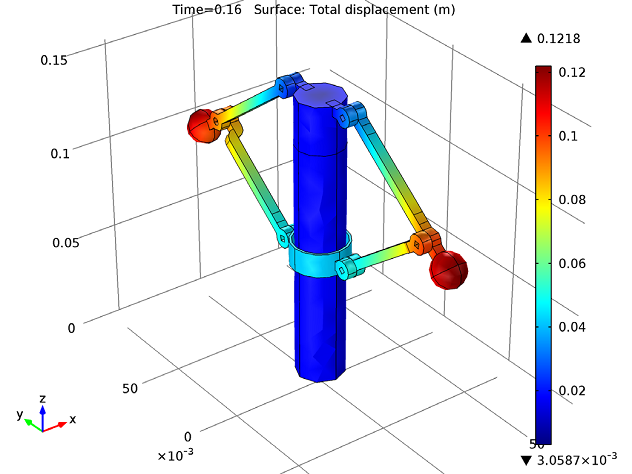
The displacement of the sleeve, flyballs, arms, and links in response to the engine speed. Colors show displacement in meters.
There is one additional part in this engine governor, namely the spring. Although you can’t see the spring in the model, imagine that it is connecting the sleeve to the top of the spindle so that as the sleeve rises up the spindle, it compresses the spring. The spring restricts the outward motion of the flyballs, and as the flyballs rise, the spring creates different equilibrium positions of the sleeve along the length of the spindle. These equilibrium positions occur at certain spindle RPM — at different speeds, the upward motion of the flyballs due to centrifugal force and the downward force of the increasingly compressed spring have a net force of zero, and the sleeve stays localized at a certain position along the spindle. Depending on the RPM of the spindle, the sleeve has different equilibrium positions along the spindle. The motion is stabilized by a dashpot acting as a damper in the system.
Simulating a Centrifugal Governor
We can use the Multibody Dynamics Module to simulate the governor’s behavior, analyze the stress in the joints, and to determine the equilibrium positions of the sleeve’s sliding motion along the spindle. In our model, hinge joints connect the arms to the flyballs, and the links to the sleeve. The sleeve itself is mounted over the spindle using a prismatic joint, and can freely slide up and down the spindle. The hinge joints in this model have one rotational degree of freedom, and the prismatic joint has one translational degree of freedom along the spindle axis.
The image below shows the von Mises stress in the arms and links of the governor, visualizing that the stress is most concentrated near the joints.
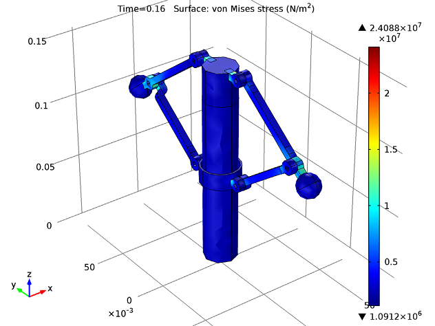
The von Mises stress on the arms and links in the engine governor.
In addition, we can use the simulation to analyze the displacement of the sleeve along the length of the spindle. In the figure below, we can see the displacement plotted against the number of revolutions of the spindle. As can be seen in the graph, there are two equilibrium positions between 0 and 8 revolutions of the spindle. Just after 2 revolutions, since the RPM of the shaft has increased, the equilibrium moves to a new position between 0.033 and 0.038 m.
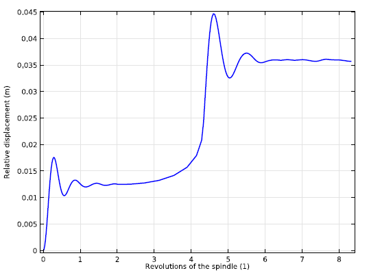
Relative displacement and equilibrium positions of the sleeve with respect to the spindle.
In the phase portrait below, we can see the relative displacement of the sleeve’s sliding motion. This graph gives us a more detailed analysis of the sleeve’s motion, and clearly shows the two equilibrium positions.
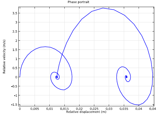
Phase portrait of the sleeve’s sliding motion along the spindle.


Comments (0)