
In the last seven years, the output of the manufacturing industry has increased by a total of around 10–20%. This growth is partly thanks to technologies and processes that save on time and costs, such as 3D printing and, as is described here, powder compaction. To model this process, we can use the new porous plasticity models in the latest version of the COMSOL Multiphysics® software.
Powder Compaction Fuels Advancement in the Manufacturing Industry
In powder compaction, a metal powder enters a die and is compacted through applied pressure. This high pressure comes from a punching tool inside the die cavity (often at the bottom surface). The powder is ejected from the cavity once it has been compacted and molded into a certain shape.
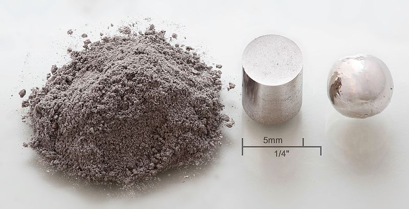
Through powder compaction, metal powders are transformed into solid components. Image by Alchemist-hp — Own work. Licensed under CC BY-SA 3.0 DE, via Wikimedia Commons.
With production rates averaging between 15 to 30 parts per minute, the powder compaction process enables manufacturers to quickly design strong components. Another benefit of this process is that it saves costs, as the component doesn’t need much additional work.
From a simulation standpoint, we need to perform a highly nonlinear structural analysis on powder compaction that accounts for:
- Contact between moving parts
- The elastoplastic constitutive law applied to the metal powder
- Geometric nonlinearity resulting from large displacements
As we demonstrate here, COMSOL Multiphysics® version 5.3 is ideal for handling such analyses.
Example Model: Fabricating a Cup with Powder Compaction
For our example, let’s consider the fabrication of a cup-shaped component via powder compaction. The model geometry includes the workpiece (metal powder in this case) and the die. Note that the punch tool is not part of the model setup. We instead apply a prescribed displacement in the normal direction to the upper and lower faces of the powder in order to compact it. Because of the axial symmetry of the model, we can reduce its size to a 2D model, thus reducing the computational time of the simulation.
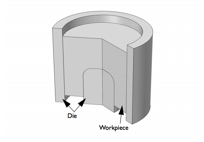
The model geometry for a powder compaction analysis.
The latest version of COMSOL Multiphysics includes five new porous plasticity models that cover various porosity values.
- Shima-Oyane
- Gurson
- Gurson-Tvergaard-Needleman
- Fleck-Kuhn-McMeeking
- FKM-GTN
These models are important for simulating powder compaction, as they allow us to accurately represent the porosity of the workpiece and produce reliable results. In this case, we combine the Fleck-Kuhn-McMeeking and Gurson-Tvergaard-Needleman models to describe an aluminum metal powder. Note that the die’s material properties assume it to be rigid.
In addition to the Prescribed Displacement boundary condition mentioned above, we also set the inner and outer dies as fixed domains.
Evaluating the Simulation Results in COMSOL Multiphysics®
From our simulation results, we can assess various properties of the metal powder at the end of compaction. To start, let’s look at the volumetric plastic strain. The strain at the center of the fillet appears to be minimal, while the strain near the ends is high. At the corner points of the workpiece, the strain is around 12% — likely the result of friction against the die.
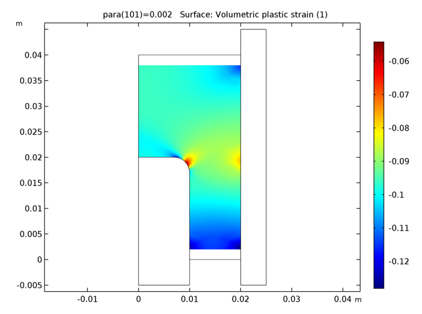
The volumetric plastic strain of the workpiece as the compaction process ends.
During compaction, the porosity of the aluminum powder decreases, while the density and strength of the component increases. Based on the geometry and loading used in this scenario, we can expect that the changes to the porosity will be nonuniform.
The plot below shows the current void volume fraction contours of the powder; i.e., the porosity of the powder. Compared to the middle and top portions of the workpiece, the metal powder in the thin lower portion is more compact. Near the central area of the fillet, the powder is less compact because of material sliding on the rounded corner. The following animation illustrates how the volume fraction evolves over time.
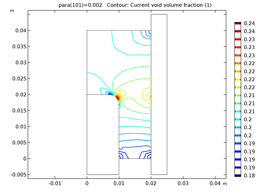
The current void volume fraction as the compaction process ends.
Changes in the volume fraction over time.
Lastly, let’s consider the von Mises stress in the workpiece. The results indicate that the stress is greater in the areas where more compaction occurs.
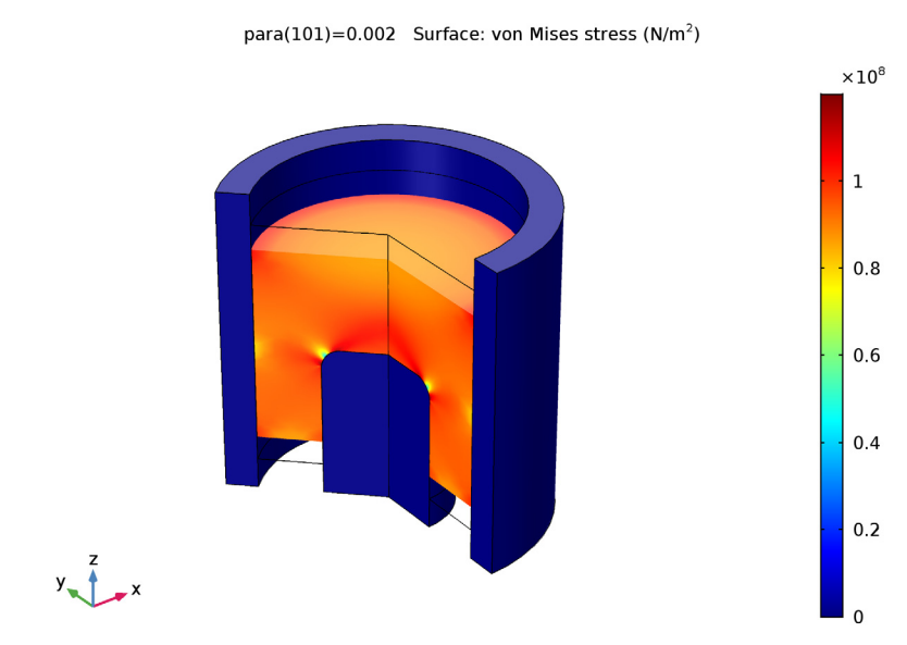
The von Mises stress within the workpiece.
Performing Powder Compaction Analyses Using Porous Plasticity Models
When simulating powder compaction, it is important to access the appropriate plasticity model that is preferably predefined in your analysis tool and available for direct use. To meet your modeling needs, COMSOL Multiphysics® version 5.3 brings you five new models that cover a wide range of porosity values.
For a helpful introduction to using these porous plasticity models, try out the example from today’s blog post.




Comments (11)
Dheya Abdulamer
August 9, 2017Is it possible solution this model by using Time dependent study.
If yes, please write tutorial.
Caty Fairclough
August 23, 2017Hi Dheya,
Thanks for your comment.
Yes, you could also run such an analysis as a time-dependent study. The question is more what is your purpose in doing so? What effects of true time do you need to model?
Dheya Abdulamer
March 6, 2018Dear Caty,
Thanks alot for your Response, I got your message now because I did not have any notification about your comment.
My purpose is measuring movement (displacement in the Y- axis ) of particles as a function of time.
The particle have coordinates in the X- axis and Y- axis which can be entered by Point data sets.
For example measuring Y- displacement of particle located on 20 mm at X- axis and 6 mm at Y axis during 3 sec of compaction process of powder.
Caty Fairclough
March 9, 2018Hi Dheya,
Thanks for the reply.
In which way is the response time dependent? Is there any time dependence (like creep, inertial effects, or explicit time dependence of material parameters) in your special version of it? If not, you should not use a time-dependent study. The model which we wrote about uses a parameter to increment the external prescribed displacement. This parameter you can think of as a ‘pseudo-time’, and you can plot the results as a function of it.
Dheya Abdulamer
March 26, 2018Hallo Caty,
Thanks for your comment.
The model I had used it was soil plasticity model (Drucker Prager match with Mohr Coloumb). The reponse of time dependent is based on interpolation functions for defining time dependent properties of sand and time dependent load. These functions can be used in blank material and boundary load repectively.
I have used porous plasticity model, modified cam clay model and Darcy s law model but the results not too much difference, still there is problem with time dependent deformation is too small, although I had applied time dependent 1 MPa boundary load .
Dheya Abdulamer
March 26, 2018Just, I ask you solve your model by time- dependent study, hopefully can I benefit from your case.
Caty Fairclough
April 17, 2018Hi Dheya,
Thanks for your response.
In principle, setting up a time-dependent analysis does not differ much from doing the parametric analysis in the original example. But the way you describe the problem, there are no time derivatives in it, so the time can just be treated as a parameter in a parametric analysis. Using a time-dependent solver to solve a problem that essentially is a sequence of stationary solutions is not optimal, since the time-stepping algorithms are tuned to work with problems containing first- or second-time derivatives.
If you have further questions, please feel free to try the Discussion Forum or reach out to our Support team.
Online support center: https://www.comsol.com/support
Email: support@comsol.com
Komlan Koumbogle
February 14, 2019Hello,
I have a question about how to applicate this tutorial to a time dependent compression of pharmaceutical powder ?
Brianne Christopher
February 14, 2019 COMSOL EmployeeHello Komlan,
Thank you for your comment.
For questions related to your modeling, please contact our Support team.
Online Support Center: https://www.comsol.com/support
Email: support@comsol.com
habib jalili
December 18, 2019Hi
I want to simulate the biological cells such as red blood cells, with thin thickness and a liquid inside the membrane. which model should I choose?
Thirupathi Nadimetla
February 2, 2021I want to use Lorentz forces to compact the powder.Pls Suggest how to do it