
Radiation effects in semiconductors is a broad and complex topic, affecting many technical areas such as the electronics industry, medical imaging, nuclear engineering, and aerospace and military applications. Here, we show you how to study the electronic response of a p-i-n diode (aka PIN diode) to ionizing radiation, based on an early paper (Ref. 1). The tutorial is available with the Semiconductor Module as of COMSOL Multiphysics® version 5.5.
Defining the Global Time Parameter
To study both steady-state and transient responses, it helps to define a global parameter t with the unit of time, and a time-dependent generation rate gR using the global parameter t and a global piecewise function pw1, which, in this model, describes a triangular pulse of peak value of unity.
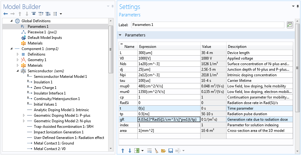
Define global parameters, in particular the time parameter t and the time-dependent generation rate gR.
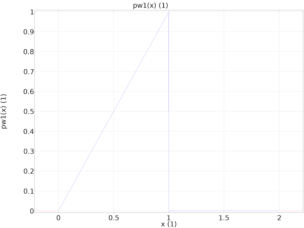
The global piecewise function pw1 describing a triangular pulse of peak value of unity.
This time parameter t lets stationary solvers recognize the built-in time variable of the same name t. This makes it possible to conveniently set up the model using the same time-dependent expression gR for the generation rate due to the radiation dosage, regardless of the study type.
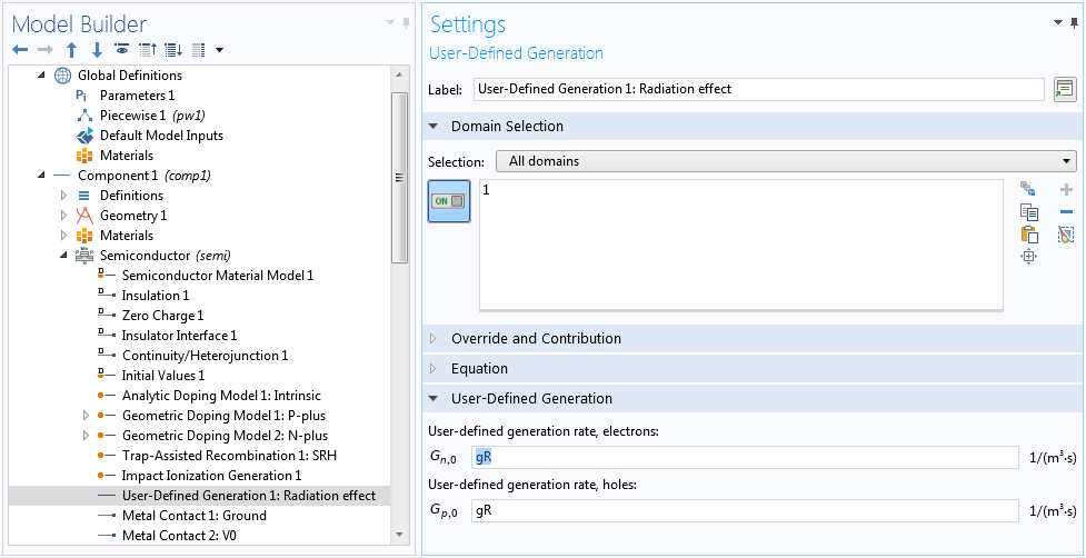
The same time-dependent expression gR for the generation rate can be used for both steady-state and transient studies.
In the case of steady-state studies, the dosage can be adjusted by setting the value of the time parameter t appropriately.
Reverse Biasing the Diode
The p-i-n diode is constructed from a 300-um-thick silicon wafer with a doping profile shown in the figure below.
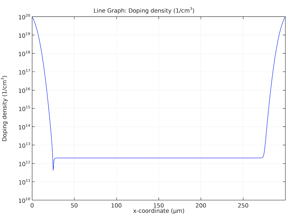
Doping profile of the p-i-n diode.
It is reverse biased to 1 kV to collect the charge carriers generated by the radiation. This is done with stationary studies in the model. The value of the time parameter t is left at the value of 0[s] as specified in the global parameter table, so that the radiation is zero (no generation) for the voltage sweep.
The field-dependent mobility model used by the paper makes the equation system very nonlinear and difficult to solve. Fortunately, there are different ways to overcome this difficulty. For example, we can first assume field-independent mobility by setting the continuation parameter cp to zero. This helps an easier ramp-up of the applied voltage V0 from equilibrium to the operating voltage of 1000 V.

First voltage sweep with field-independent mobility by setting the continuation parameter cp to zero.
At this step, it also helps to change the continuation predictor from the default Constant to Linear. The Linear option helps accelerate the voltage sweep by using a linear extrapolation scheme to estimate the initial guess for the next swept parameter. The default Constant option uses the current solution as the initial guess for the next swept parameter, which is a more conservative approach and in most cases is appropriate for the highly nonlinear semiconductor equation system — but for this model, it is too conservative.

Select the Linear predictor.
After the voltage sweep is completed with field-independent mobility, we can use the set of solutions as the initial guess for the case of the full mobility model with field dependence. This is done by using a Parametric Sweep node to pair the swept voltage V0 with a swept parameter index.

Pair the parameter index with the swept voltage parameter V0.
Then, use the parameter index to select the correct solution corresponding to each V0 value, using the Manual option in the settings window for the Step 1: Stationary node.
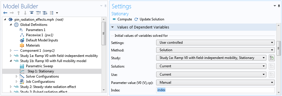
Indexing the solution for each voltage value.
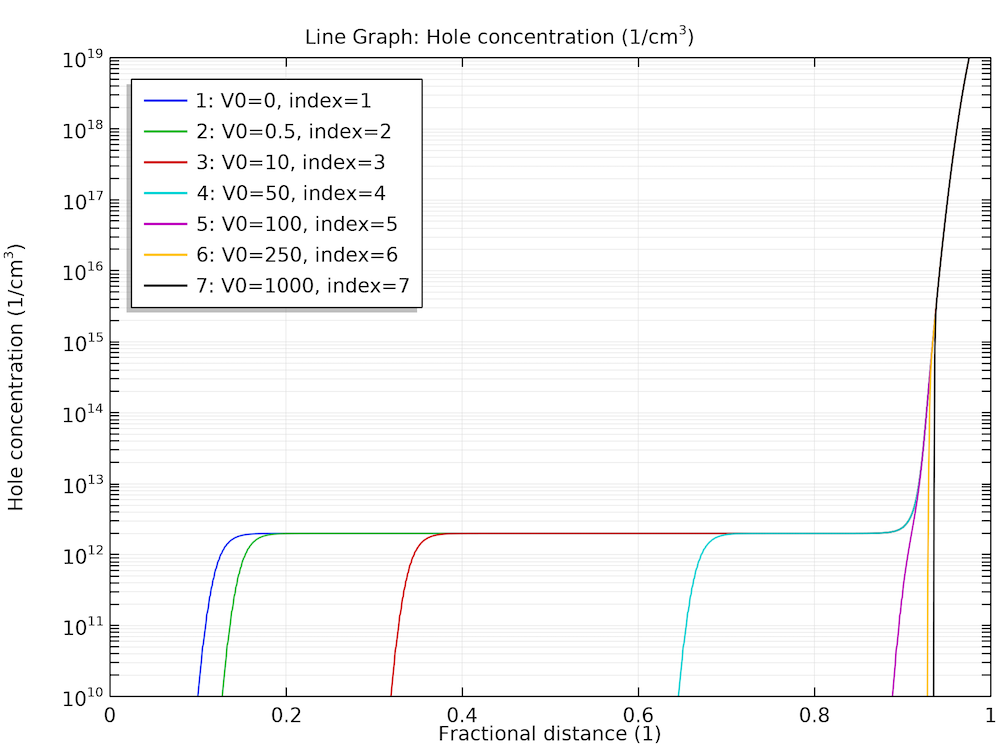
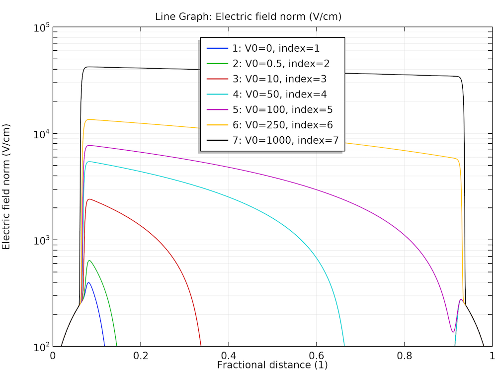
Once the study is computed, the depletion of the carriers and the buildup of the electric field can be plotted, as shown below. We see that at the end of the voltage sweep the hole is completely depleted and the electric field is roughly constant, as one would expect.
Voltage sweep results for carrier depletion (left) and field buildup (right).
Steady-State Response
With the diode fully reverse biased at 1000 V, we are ready to study the response of the device to steady-state radiation. As mentioned earlier, in previous studies the time parameter t was 0[s] as defined in the global parameter table, thus, the pulse function pw1(t/tp) was zero and the generation rate due to radiation gR was also zero. Now, to specify nonzero radiation, just set the time parameter t to the pulse duration tp, so that the pulse function pw1(t/tp) is unity. Then, the dosage rate can be specified by the parameter RadSi directly in units of Rad(Si)/s.

Set the time parameter t to the pulse duration tp, then use the parameter RadSi to specify the dosage rate.
As we will see, the field-dependent mobility gives rise to an interesting result for high dose rates; however, it also makes the equation system very nonlinear and difficult to solve. In the previous pair of studies for voltage sweep, this difficulty is overcome by separating the solution process into two stages, with field-independent mobility in the first stage and full mobility in the second. In this current study of dose rate sweep, we show an alternative method to overcome the difficulty by using a single study with full mobility.
The nonlinearity causes the Automatic Newton solver to converge slower than the ideal quadratic convergence behavior, which in turn causes the continuation solver to take too-small steps for the swept parameter RadSi. Instead, we can use the Constant Newton option with an appropriate damping factor. In addition, we provide a better initial step size for the continuation solver under the Parametric 1 node to prevent it from taking too large a first step and then waste time in backtracking. Finally, you can use Anderson acceleration to further improve performance (by taking advantage of the information from earlier history of the nonlinear iteration), and use a smaller max number of iterations to reduce the time wasted in backtracking.

Use the Constant Newton method with a small damping factor and Anderson acceleration scheme to overcome nonlinear difficulties.

Optimize step size for the continuation solver.
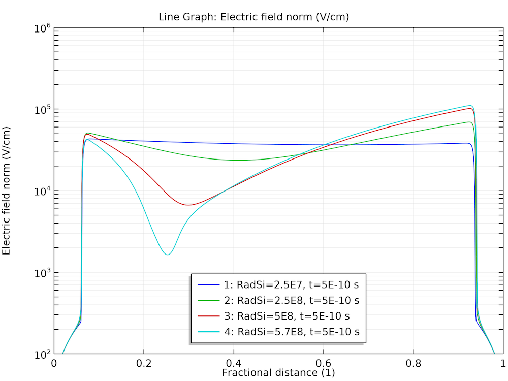
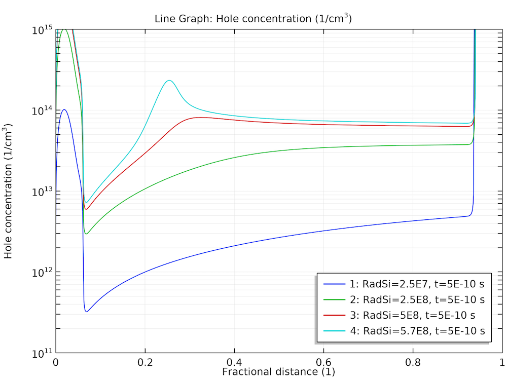
After computing, plot the steady-state electric field distribution and hole density profile for several ionization rates, as shown below.
Steady-state response at various dose rates for the electric field (left) and hole density (right).
At high dose rates, the separation of the generated charge carriers causes the electric field to diminish in the bulk of the diode. The corresponding small drift velocity leads to the pileup of charge carriers in the same bulk region. This effect is expected to slow down the time response, as will be shown next.
Time-Dependent Response
After completing the steady-state study, we are now ready to investigate the effect of pulsed radiation with the triangular waveform given by the inset of Fig. 8 in the reference paper. This waveform is provided by the pulse function pw1(t/tp) in the model with a normalized height of unity. The peak dose rate is specified by the parameter RadSi in units of Rad(Si)/s. We tighten the time-dependent solver tolerance to 1e-8 and use the Initial value based scaling for the dependent variables, since the initial condition is provided by the solution of the stationary study and the transient effect is a small perturbation in terms of the overall scales of the dependent variables. Also, we can use an Events interface to capture the abrupt change in the slope at the end of the applied radiation pulse.

Use an Events interface to mark the end of the radiation pulse.
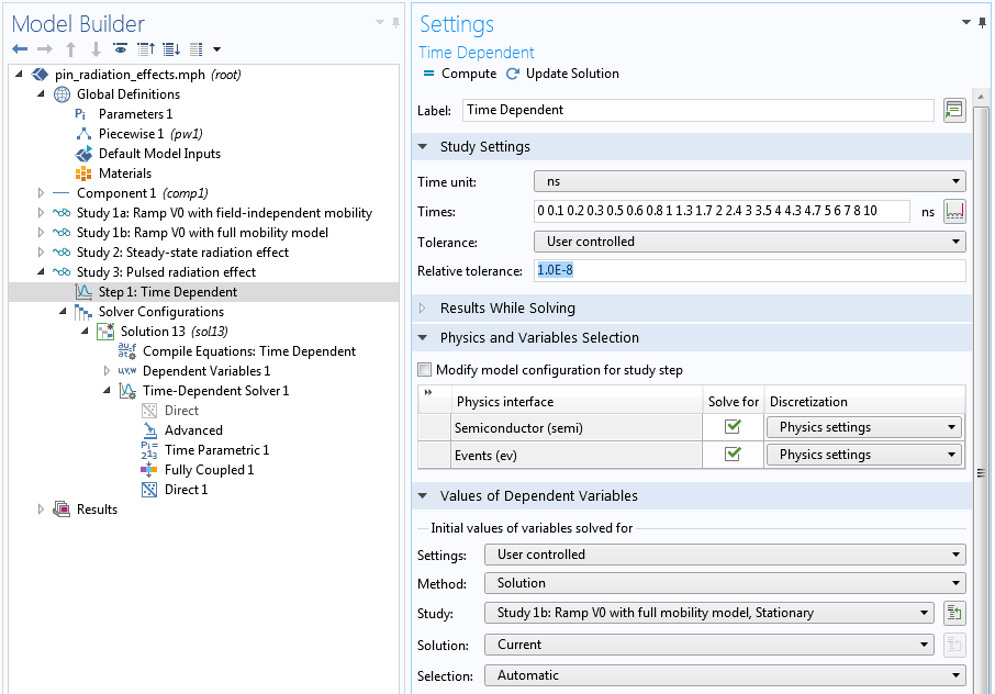
Tighten the time-dependent solver tolerance to 1e-8, and use the solution from the stationary study as the initial condition.
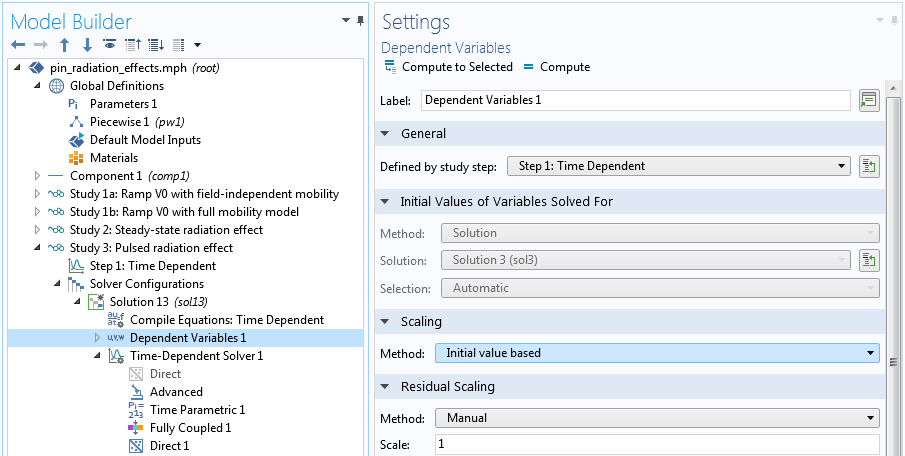
Use the Initial value based scaling for the dependent variables.
The transient study shows a significant tail of the photocurrent waveform for the larger dose rate (green curve below), as compared to the result of the smaller dose rate (blue curve below).
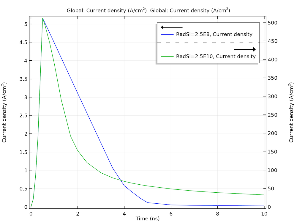
Simulated photocurrent response shows a significant tail for the larger does rate (green) as compared to the one for the smaller dose rate (blue).
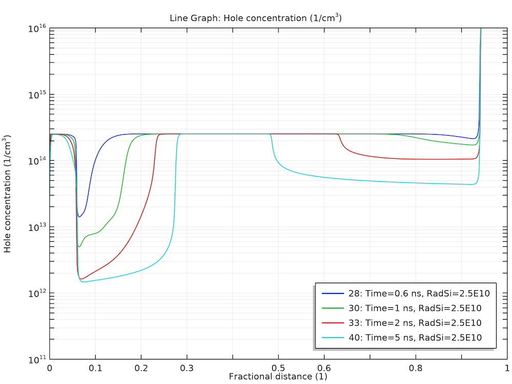
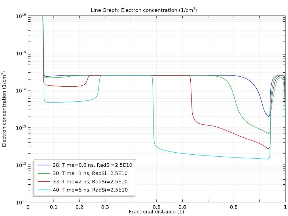
This behavior can be understood by examining the plots of electric field and carrier concentrations below. As the electrons and holes are swept by the electric field in the opposite directions, the charge separation causes the electric field to diminish in the bulk. This leads to a much smaller drift velocity in the same bulk region, thus, the charge carriers stay in that region for a much longer time.
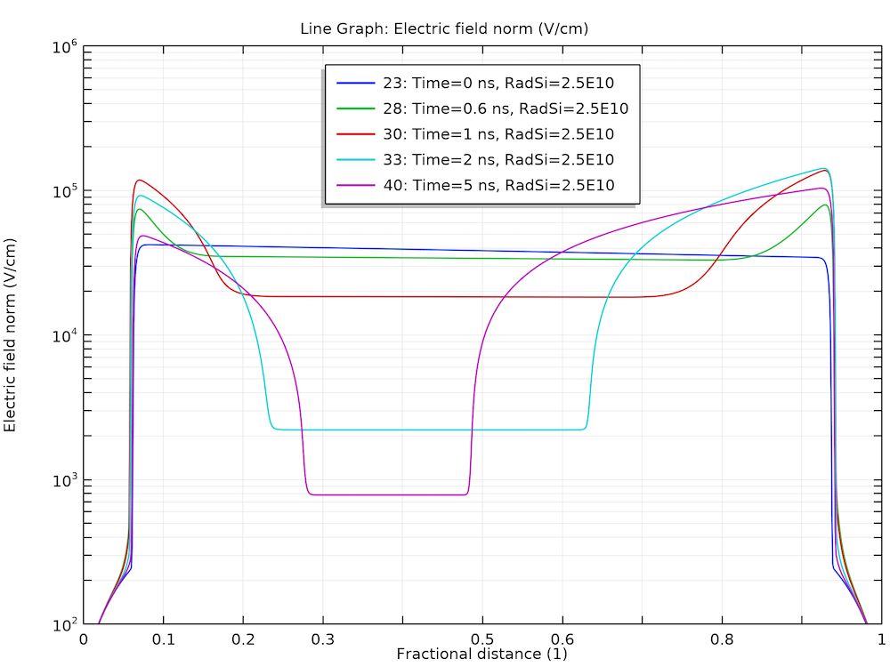
Diminishing of the electric field in the bulk.
Stagnation of the charge carriers in the bulk for the holes (left) and electrons (right).
Using the versatile postprocessing tools in COMSOL Multiphysics®, we can easily make a summary plot to encapsulate all of the essential information, as discussed above.
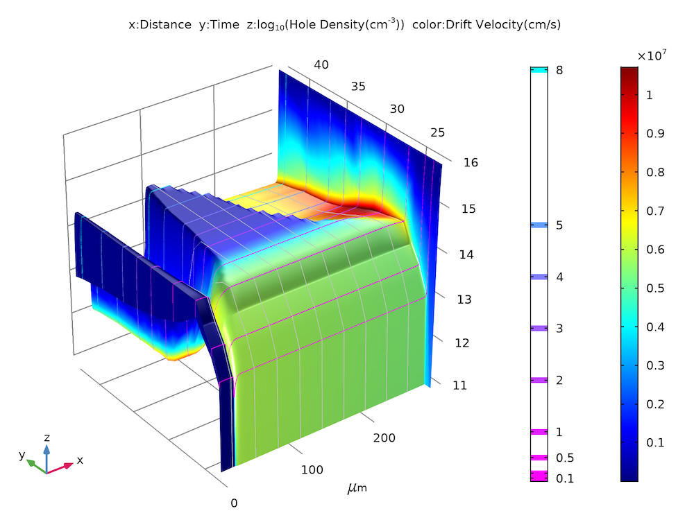
Summary plot of hole density (z-height) and drift velocity (color) as functions of time (y-axis).
Concluding Thoughts
We showcased some practical modeling techniques using a tutorial model of a p-i-n diode and its steady-state and transient responses to ionizing radiation. The simulation results match well with the figures published in the reference paper.
Next Steps
To try the model yourself, click the button below (note that you need to log into a COMSOL Access account with a valid license to access the MPH file):
Reference
- C.W. Gwyn, D.L. Scharfetter and J.L. Wirth, “The Analysis of Radiation Effects in Semiconductor Junction Devices,” IEEE Conference on Nuclear and Space Radiation Effects, Columbus, Ohio, July 10–14, 1967.




Comments (4)
Aditya Kalavagunta
February 10, 2020This looks great Chien!
Chien Liu
February 11, 2020 COMSOL EmployeeThanks Aditya! Chien
Adam Wolverton
April 21, 2020Great work. I was wondering if you have any suggestions for simulating electrical properties of scCVD diamond exposed to high energy neutrons(14.1 MeV)? Essentially, this is a neutron detector. Diamond geometry is 500um thick and 4mm x 4mm and is metalized on each side like a parallel plate capacitor. It has been observed that gain can be achieved through an avalanche effect due to impact ionization when a high enough voltage bias is place across the diamond. I am having issues trying to set up a simulation to get a photocurrent plot. Essentially, when the neutron interacts with diamond, the majority of the photocurrent generation is due to elastic scattering of recoiled Carbon-12 ions. Is there a way to randomly distribute energy depositions of 2 MeV within a volume of diamond? Any suggestions would be helpful.
Chien Liu
April 21, 2020 COMSOL EmployeeDear Adam, Yes you should be able to specify a user-defined generation term that is both space- and time-dependent. If you need further assistance, please contact us at http://www.comsol.com/support . Sincerely, Chien