
Commonly used in the automotive industry, snap hooks are a type of fastener that involve the insertion of a hook into a slot. When designing snap hooks, it is important to analyze the forces required for the insertion of the hook as well as its removal. We can address this through simulation.
Fasten Your…Control Panel
A vehicle’s dashboard provides valuable information for a driver, from indicating the speed of the car to gauging its fuel levels. What’s as important as the instruments themselves is the manner in which they are installed. In many cases, fasteners known as snap hooks are used in the design of a car’s control panel, ensuring that the different components are securely fixed.
When inserting a snap hook into its slot, an important consideration is the force that needs to be applied to insert the hook into the slot as well as the force that is required to remove it. With COMSOL Multiphysics FEA software, you can study these forces and the resulting stresses and strains in the hook.
Inserting a Snap Hook into Its Slot
In the Snap Hook model, we leverage the snap hook’s symmetry to analyze only half of its original geometry in an effort to decrease the size of the model. The snap hook is assumed to be composed of an elastoplastic material featuring isotropic hardening and a constant tangent hardening modulus. Meanwhile, the lock is assumed to be rigid when compared to the hook, with the space behind the lock representing the slot into which the hook should lock.
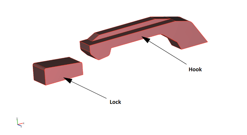
Model geometry.
Several boundary conditions are applied to the model, as shown in the schematic below. For boundaries in the symmetry plane, a symmetry boundary condition is used. A fixed boundary condition is implemented for the face of the lock, where it is attached to the remainder of the geometry of the locking mechanism (not modeled here). Lastly, a prescribed boundary condition is applied where the face of the hook meets the rest of the geometry.
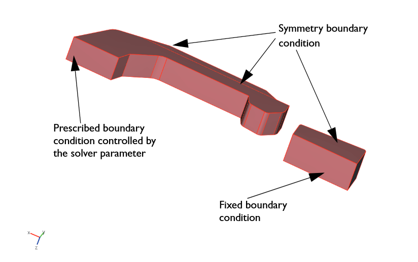
The applied boundary conditions.
Evaluating Stresses and Strains
Before insertion into the slot, we first measure the equivalent stress levels in the hook. As indicated in the following plot, the maximum equivalent stress levels occur at parameter step 0.84. This parameter represents the point right before the hook enters the slot. Note that when passing over the edge, the hook is bent upwards. The elastic forces will tend to press the hook into the slot before it “fits.” If holding the hook, you would be pushing up until this point; however, here the hook would actually be pulled away from your hand.
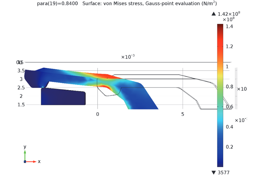
The hook’s equivalent stress levels prior to entering the slot.
The next graph depicts the degree of force needed to insert and remove the fastener as a function of the parameter step. When the parameter value varies from 0 to 1, the hook is moved inwards at a constant rate to eventually sit in the slot. Then, between the parameter values 1 and 2, the hook is pulled back out of the slot.
At the parameter value 0.2, the hook first comes into contact with the fixed locking mechanism. The force rises steeply, while the hook tip is forced upwards. In reality, the hook would snap into place after reaching the peak force of around 2.5 N at the parameter value 0.23. Since we control the displacement in the simulation, we can follow the force throughout the entire process. Between the parameter values 0.7 and 0.9, the hook slides down on the back side. The change in the sign of the force indicates that the hook is actually pulled into the slot by a combination of the geometry and the elastic forces.
When trying to pull the hook back out of the slot (at parameter values greater than 1), we must apply a load that is three times higher — about 7.5 N — to remove the hook from the slot (at a parameter value of about 1.12). This is a desirable feature of a hook designed for a locking mechanism.
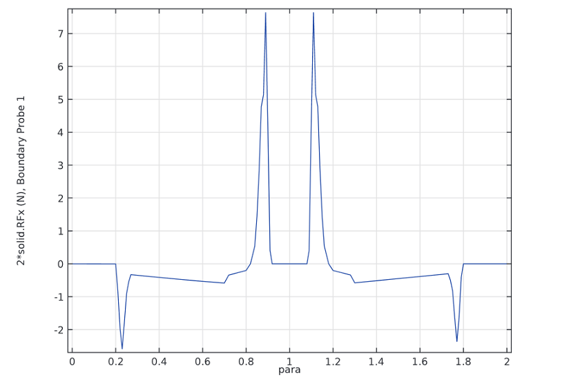
Force required for the insertion and removal of the snap hook. The first positive peak in the graph can be attributed to the elastic forces pushing the hook into the slot before it “fits.” Following retraction, the hook hits a steep surface, which results in the second positive peak in the graph. After passing the corner (represented by parameter 1.2), the hook is pressed out by itself, or a negative force.
Upon its removal from the slot, the hook is shown to have a volume in which there are plastic strains, as illustrated in the plot below. Thus, we can conclude that after inserting the hook into the slot, it is permanently deformed.
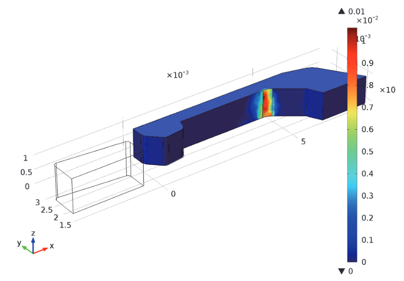
The hook’s effective plastic strain following its removal from the slot.
Concluding Thoughts
In this blog post, we have explored the role of simulation in addressing the forces behind the insertion and removal of a snap hook into a slot. By analyzing such forces, you can enhance the design of snap hooks to ensure that they provide continuous security while also being able to remove them without causing damage to the fastener. This is particularly relevant within the automotive industry in cases where certain parts of a vehicle’s control panel need to be repaired or replaced.
Further Reading
- Model download: Snap Hook
- Related blog post: Why All These Stresses and Strains?


Comments (0)