
Say you’re riding a bicycle and someone gives you a push from the side. To quickly stabilize yourself, you turn the handlebar of the bicycle in the same direction to counteract the fall. While riders do this instinctively, what’s fascinating is that our bicycles can do the same thing. Modern bicycles are designed to be self stable; they’re good at keeping balance while moving uncontrolled. Let’s take a look at how we can simulate this effect in COMSOL Multiphysics.
What We Know About Bicycle Self-Stability
The modern bicycle hasn’t really changed much since the safety bicycle, an early bicycle design that came into use in the 1880s. Over a century later, scientists are still trying to work out what makes a bicycle self stable. In other words, how does an uncontrolled bicycle keep balance and stay upright? Numerous papers explain the dynamics of bicycle motion through analytical equations. One of the earliest notable works is a paper by Francis Whipple in which he derived general nonlinear equations for the dynamics of a bicycle with a leaning, hands-free rider.
The long-standing consensus has been that a bicycle is stable because of two factors: the gyroscopic precession of the front wheel and the caster effect, or trail, as a result of the front steer axis meeting the ground ahead of the front contact point. More recently, a team of researchers from Delft and Cornell (see Reference 3) published a comprehensive review on the linearized equations of the motion of the Whipple bicycle model. They used their findings to present on bicycle self-stability. Their study shows that there isn’t one simple reason for this phenomenon. A combination of factors, including gyroscopic and caster effects, bicycle geometry, speed, and mass distribution come into play to keep an uncontrolled bicycle upright.
Inspired by their research, we developed a multibody dynamics model to demonstrate the self-stable riding of a bicycle with a hands-free rider.
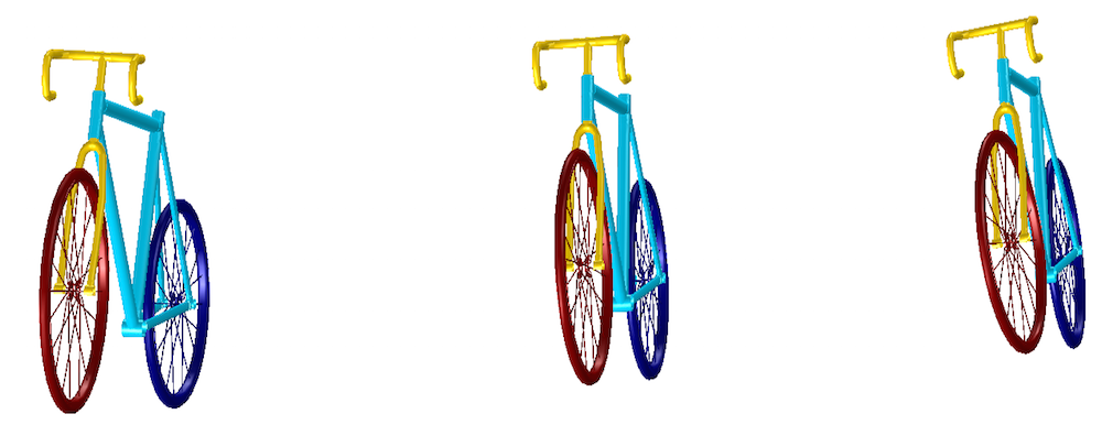
The motion of a bicycle at different time instances.
Multibody Model of a Bicycle
This tutorial model of a bicycle demonstrates the motion of a bicycle with a hands-free rider on a flat surface when perturbed with a lateral force to produce a lean about the forward-riding direction. We extended the analysis to study the self-stability of the bicycle when the forward speed and front steer axis tilt vary.
To set up the bicycle model, we make the following assumptions:
- All of the components are assumed rigid.
- All of the joints are considered frictionless.
- The wheels of the bicycle are modeled assuming knife-edge contact with the ground.
- Pure rolling constraints are implemented for the wheels.
- The bicycle is assumed to move on a flat surface.
- The bicycle model assumes a hands-free rider, defined through added mass on the rear frame.
The bicycle comprises four rigid components: the rear wheel; the rear frame, including the hands-free rider; the front frame, including the handlebar; and the front wheel. Although wheels have a finite thickness, the formulation assumes a single point of contact with the ground. The rear frame connects to the rear wheel through a hinge joint. Another hinge joint connects the two frames. The axis of this joint forms the steer axis of the bicycle. A third hinge joint connects the front wheel and the front frame.
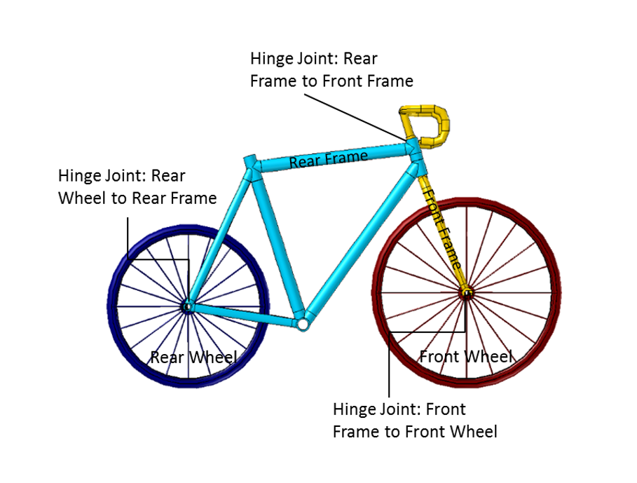
The geometry of a bicycle in COMSOL Multiphysics.
The bicycle geometry used in this model is shown above. The inertial properties of the bicycle’s components are defined in terms of mass, moments of inertia, and the center of mass location. The important geometry parameters are the wheel radii, wheelbase (wb), and steer axis tilt (st). The steer axis tilt controls the trail (c).
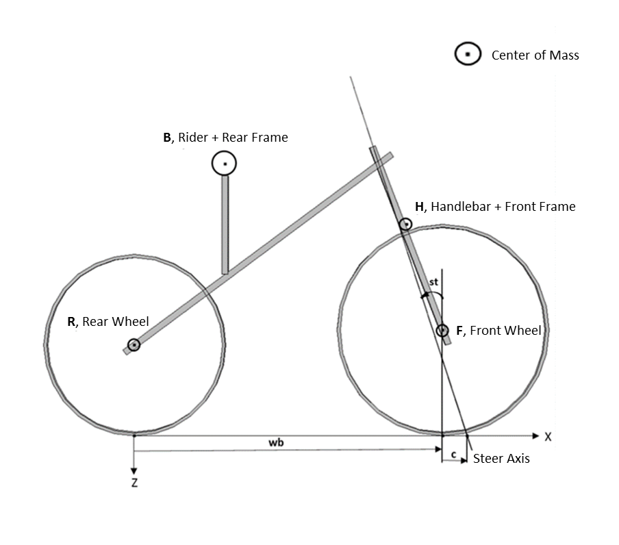
The schematic of a bicycle.
As mentioned earlier, a pure rolling motion is assumed between the wheels and the ground. In the case of pure rolling, the velocity at the point of contact with the ground is zero. In this model, the wheel rolling is implemented without the use of any contacts to reduce the computational cost. Instead, we use an alternative multibody dynamics approach to model this motion. To describe the yaw, lean, and spin motions of the wheel, three hinges and three corresponding massless links are created. We implement three no-slip constraints to restrict the wheel slip in the forward, in-plane lateral, and out-of-plane directions. Since it is not possible to apply constraints on velocity, we convert them into displacement constraints.
Below, we describe the process for setting up these constraints, which have also been explained in more detail in the Rolling of a Rigid Wheel tutorial model.
To ensure the pure rolling of the wheel, we need three constraints to restrict the wheel slip in three directions.
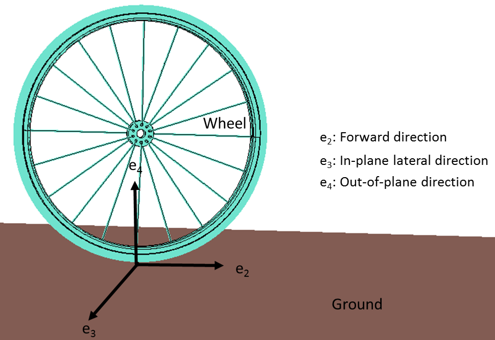
The wheel model, showing the three constraint directions.
These constraints are as follows:
No slip in the forward direction:
No slip in the in-plane lateral direction:
No slip in the out-of-plane direction:
where \bold{e}_{2}, \bold{e}_{3}, and \bold{e}_{4} are the instantaneous forward direction (lean axis), in-plane lateral direction (spin axis), and out-of plane direction (\bold{e}_{4}=\bold{e}_{2} \times\bold{e}_{3}), respectively; \frac{d\bold{u}}{dt} is the translational velocity at the CG; r is the wheel radius; \frac{d\bold{\theta}_{s}}{dt} is the spin angular velocity; and \frac{d\bold{\theta}_{l}}{dt} is the lean angular velocity.
As it is not possible to apply constraints on velocity, these constraints are discretized in time and implemented as follows:
where \bold{u}_{p}, \bold{\theta}_{sp}, and \bold{\theta}_{lp} are the displacement vector, spin, and lean angles at the previous time instance, respectively.
These time-discrete, no-slip constraints require the previous configuration of the wheel. The rigid body translation, rotation, and the instantaneous axes of the previous step are stored by using global equations and the Previous Solution node in the time-dependent solver.
Simulating the Motion of a Self-Stable Bicycle
We chose a bicycle with a steer tilt of 18° for this analysis. The bicycle is given an initial forward velocity of 4.6 m/s. After 1 second, the bicycle is perturbed through a force of 500 N, applied for a very short period of time. This force produces a lean about the forward axis.
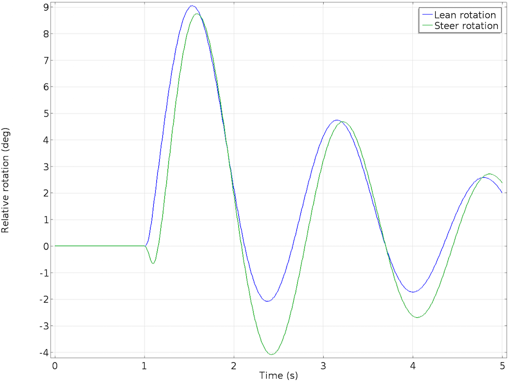
For the first second, the bicycle moves forward along the initial forward direction at a constant speed. Next, the lateral force causes the bicycle to start leaning. The cyclist is hands free and cannot steer to balance the bicycle. What happens now? We observe that as the bicycle starts leaning, the handlebar starts steering in the same direction of the fall. This corrective action of steering towards the fall causes the bicycle to start straightening itself.
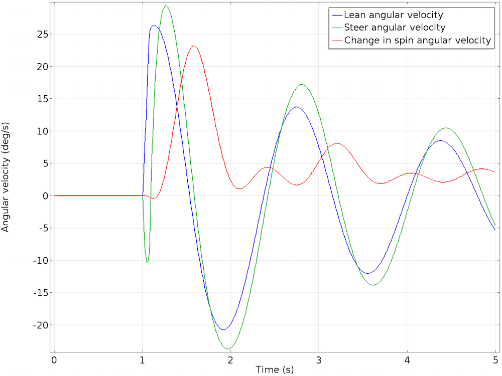
As the bicycle continues to move forward in a different forward trajectory, it starts leaning in the opposite direction. The lean is smaller in magnitude, with the steer motion closely following the lean with a slight phase lag. This back-and-forth leaning and steering perturbation continues and eventually damps down. The bicycle moves forward in an upright position and acquires a slightly increased forward velocity. The oscillations in lean and steer angles, as well as angular velocities, progressively damp and die out.
Motion of a bicycle with a hands-free rider on a flat surface when leaned about the forward axis. Here, the arrow indicates the lean of the bicycle.
The results of the lean and steer rotation (left) and relative angular velocity (right) of the bicycle.
Performing a Stability Analysis
So far, we have learned that the bicycle has the ability to be self stable. Research tells us that there isn’t just one parameter that influences the stability of a bicycle. The bicycle’s geometry, mass distribution, and forward velocity are all responsible for its stability. To gain some understanding of this, we conducted a further analysis to study the effect of two parameters: the initial forward velocity and the steer axis tilt. We used the bicycle model mentioned above, which has an 18° steer axis tilt and a forward riding speed of 4.6 m/s, as a reference configuration and conducted a parametric analysis to study the effect of these two factors.
Initial Forward Velocity Variation
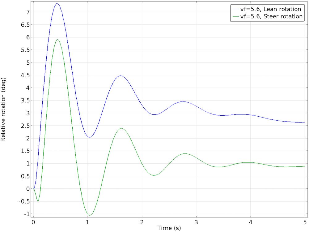
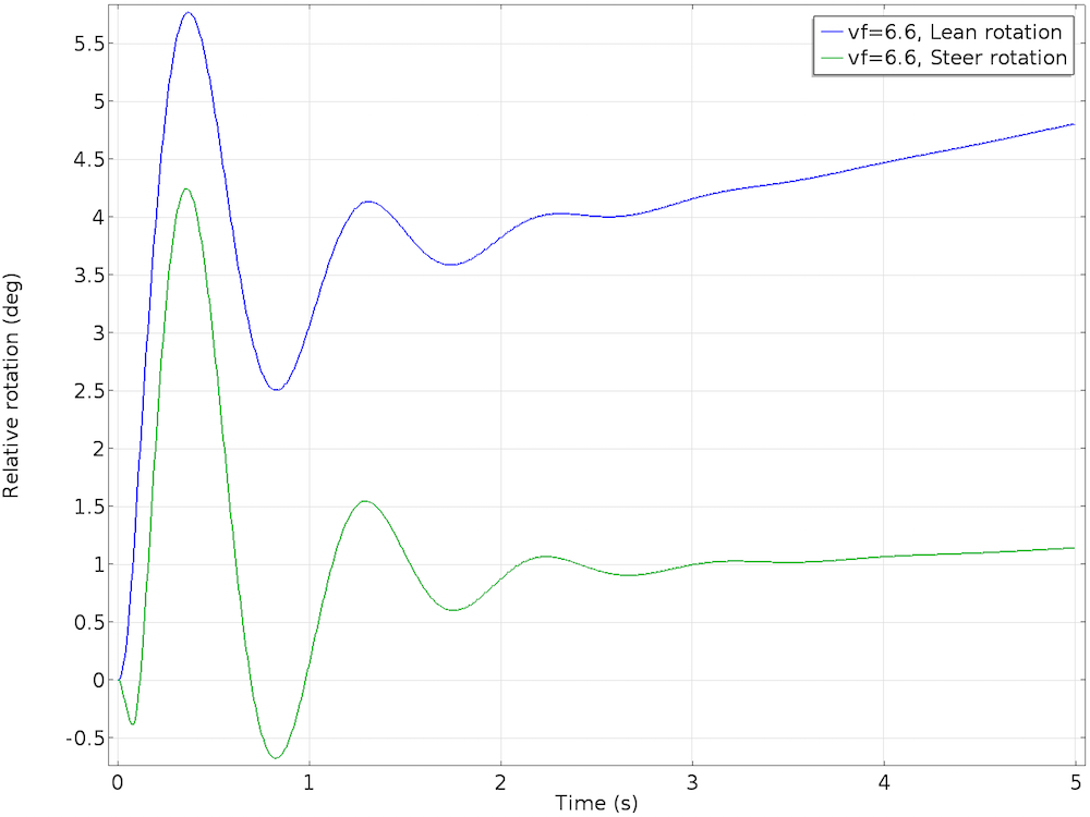
A bicycle has no way of staying upright when stationary. In order to study the effect of bicycle speed, we varied the initial forward velocity of the bicycle from 2.6 m/s to 6.6 m/s in steps of 1 m/s. At 2.6 m/s and 3.6 m/s, the bicycle leans too much and is unstable. At 5.6 m/s, the bicycle’s lean velocity damps to zero, but the lean angle acquires a nonzero value. Although this is a stable configuration, the bicycle will move in circles with a slight lean. At 6.6 m/s, the lean and steer angles increase with time, making the motion of the bicycle unstable.
| Unstable | Stable | Unstable | ||
|---|---|---|---|---|
| 2.6 m/s | 3.6 m/s | 4.6 m/s | 5.6 m/s | 6.6 m/s |
The stable case, with an initial forward velocity of 5.6 m/s (left) and the unstable case, with an initial forward velocity of 6.6 m/s (right).
Steer Axis Tilt Variation
The steering assembly is quite important for bicycle self-stability. If the bicycle is not allowed to steer (for instance, if the handlebar is jammed), then the bicycle has no way of counteracting the lean, so it will fall. In relation to this, the steer axis tilt, which controls the trail, plays a role in bicycle self-stability.
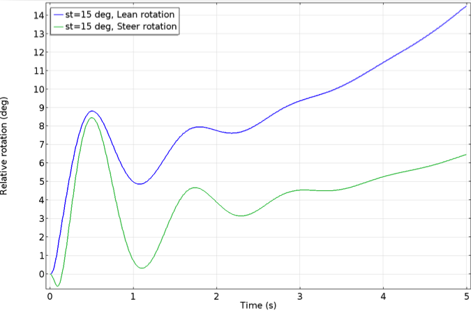
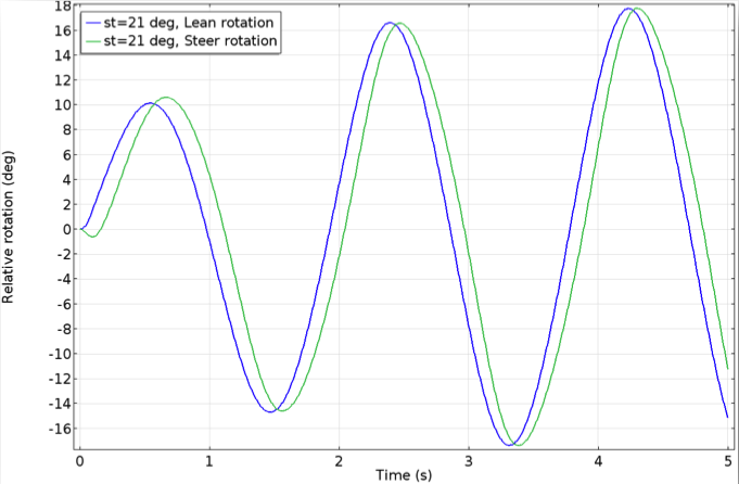
In this analysis, we varied the steer tilt from 15° to 21° in steps of 1°, thereby varying the trail to study its effect on the stability of the bicycle. At a 15° tilt, the lean and steer angles keep increasing with time, making this configuration unstable. The bicycle remains stable in the range of 16° to 19° and unstable for larger angles. For a steer tilt greater than 19°, the lean and steer angles oscillate and these oscillations increase with time, causing the bicycle to be unstable.
| Unstable | Stable | Unstable | |||||
|---|---|---|---|---|---|---|---|
| Tilt | 15° | 16° | 17° | 18° | 19° | 20° | 21° |
| Trail | 0.066 m | 0.0706 m | 0.0753 m | 0.08 m | 0.0848 m | 0.0896 m | 0.0945 m |
Two unstable cases, with the steer axis tilt at 15° (left) and 21° (right).
Concluding Remarks on Using Multibody Dynamics Analysis to Study Bicycle Self-Stability
In this blog post, we have described how you can simulate the motion of an uncontrolled, self-stable bicycle through the Multibody Dynamics Module in COMSOL Multiphysics. We have shown how to implement no-slip constraints on a rigid wheel through equations and then couple these constraints with a multibody model of a bicycle. We then analyzed the effect of initial forward velocity and steer axis tilt on the self-stability of the bicycle. By evaluating these parameters, we have seen that a bicycle that is stable in one configuration becomes unstable in another.
Bicycle self-stability is an effect of a combination of factors. Through our analysis, we concur with prior research by demonstrating that a bicycle’s stability is related to its ability to steer in the same direction as the lean.
Additional Reading
- Tutorial model: Rolling of a Rigid Wheel
- Tutorial model: Simulating the Motion of a Bicycle on a Flat Surface
- Meijaard, Jaap P., Jim M. Papadopoulos, Andy Ruina, and Arend L. Schwab. “Linearized dynamics equations for the balance and steer of a bicycle: a benchmark and review.” In proceedings of the Royal Society of London A: Mathematical, Physical and Engineering Sciences, vol. 463, no. 2084, pp. 1955-1982. The Royal Society, 2007.
- Blog post: Using the Previous Solution Operator in Transient Modeling




Comments (2)
Shane Kennedy
March 18, 2016A very simple experiment which will demystify this matter. Ride a bike, preferably a motor bike, on a straight road. At maybe 50MPH, take your hands of the handlebars. If you have a friction adjustment on the throttle, that will help. Now apply a little pressure back or forward, on one side only. This is pressure, not forcing movement, then alloy physics to determine displacement. What will happen is that your pressure upsets the equilibrium briefly. The pressure will actually cause a change of direction, in the opposite direction, and move the handlebars against the pressure. As long as you keep the pressure there, the opposite turn will increase. When you release the pressure, the bike will bring itself upright again.
Pawan Soami
March 28, 2016 COMSOL EmployeeDear Shane,
Thanks for sharing this nice experiment. I think it would be a great idea to simulate this experiment using COMSOL bike model to gain more insight in this phenomenon.
Regards,
Pawan Soami
COMSOL