
Underground medium voltage cables are often used to deliver electrical power from a transmission system and into the home of consumers. In the United Kingdom, these cables carry hundreds of amps at voltages between 11 and 33 kV, a typical voltage of electrical transmission cables around the world. Analyzing the stresses that these cables are exposed to over their lifetime is important for ensuring both consumer safety and energy efficiency. Researchers from the Glasgow Caledonian University in Scotland used COMSOL Multiphysics to create simulations that measured the fatigue caused both by the thermal and electrical stresses in underground medium voltage cables.
Simulating an Underground Medium Voltage Cable
Replacing underground medium voltage cables can be both time consuming and costly, and requires a disruption of service to customers as the cables are being replaced. Because of this, many electrical cables in the UK have been in use for 50 years and are now operating past their design life. In order to find a reliable way to monitor their condition and prioritize the replacement of these cables, researchers from Glasgow Caledonian University created integrated simulations that model the failures of underground medium voltage cables due to both electrical and thermal stresses over the lifetime of the cable. Their paper, “Failure Modes of Underground MV Cables: Electrical and Thermal Modelling” was presented at the COMSOL Conference 2009 Milan.
The paper outlines two different simulations that demonstrate the stresses on the cable over different time scales. The first simulation analyzed the thermal responses in the cable over a seven-day period with diurnal variation. The second simulation measured the electric field stress within the cable over a single AC cycle, a period of around 20 ms. The simulations were conducted in a three-phase Paper Insulated Lead Covered (PILC) cable, shown below.
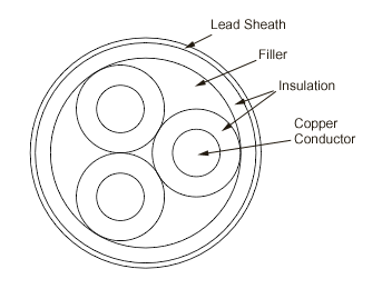
Geometry of three-phase Paper Insulated Lead Covered (PILC) cable. The insulation is made up of wound, oil impregnated paper tape. Image provided by: Peter A Wallace, Mohamed Alsharif, Donald M Hepburn, and Chengke Zhou, Glasgow Caledonian University.
Thermal Stress in Medium Voltage Cables
The first model consisted of a 6 m diameter semicircle surrounded by soil and trench-fill material, and tested the thermal stress in a buried PILC cable. The thermal conductivity in the coil was assumed to be 0.16 Wm-1K-1, and the thermal conductivity of the soil and sand was set at .02 Wm-1K-1 and 0.833 Wm-1K-1, respectively. There are several factors the researchers noted as important when determining the thermal behavior of the cable. These include the cable construction, installation, thermal properties in the soil, assumed ampacity, and ambient temperatures affecting the cable, and each of these effects were taken into account in the simulation. First, the cable system was analyzed when exposed to a steady load of 100 amps, and the following results were obtained:
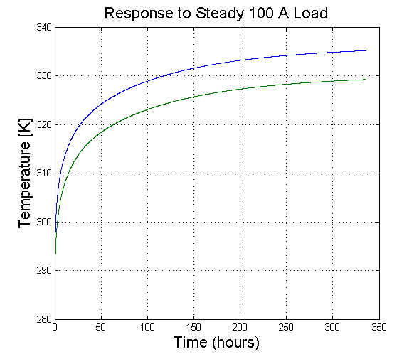
Thermal response of the cable to a 100 load and an ambient temperature of 288 K over about two weeks. Image provided by: Peter A Wallace, Mohamed Alsharif, Donald M Hepburn, and Chengke Zhou, Glasgow Caledonian University.
In the graph, the upper curve represents the temperature at the conductor core, and the lower curve represents the temperature at the surface of the cable sheath. These two curves show the gradual heating of the sheath compared to the rapid heating of the interior of the cable. As the graph shows, the system has still not reached equilibrium even after two weeks, although a steady temperature difference of 10 K has been established.
Next, the researchers measured the temperature change when the system was exposed to a diurnal load variation.
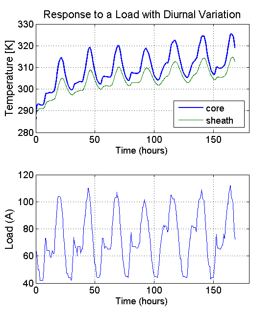
Thermal response of the cable to a diurnal and an ambient temperature of 288 K over one week. Image provided by: Peter A Wallace, Mohamed Alsharif, Donald M Hepburn, and Chengke Zhou, Glasgow Caledonian University.
This simulation produced results that corresponded to the steady load analysis. At the end of one week, the cable had reached a final maximum temperature of 326 K, and the difference in temperature between the cable and surroundings varied between 2 and 10 K depending on the load conditions.
Electrical Stress in the Cables
In the electrical stress simulation, Glasgow researchers pointed to the degradation of the electrical insulation between the conductors as one of the main reasons why underground medium voltage cables fail. This degradation is often due to the occurrence of partial discharge activity, which is caused by electrical fields that develop around bubbles or defects within the cable. These defects create a void in the cable that has a lower electric permittivity than the insulating material and thus cause partial discharge to occur, which can further degrade the cable. The figure below shows a flawless cable without voids.
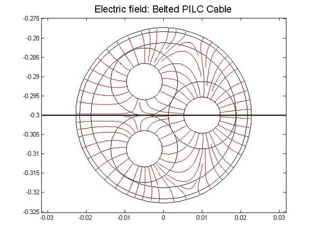
Electrical field distribution in an ideal, flawless cable, shown at the point in the AC cycle when the potential of the right hand conductor is at its highest value. The black line represents the horizontal axis of symmetry. Image provided by: Peter A Wallace, Mohamed Alsharif, Donald M Hepburn, and Chengke Zhou, Glasgow Caledonian University.
In order to test what would happen to the cable when partial discharge occurred, a 0.5 mm diameter void was introduced to the right-hand conductor within the insulation belt of the cable. The void was placed along the horizontal axis of symmetry at the point where the conductor located at x = 0.1 m is at its maximum (negative) potential. The change in the electric field due to the void can be seen in the graph below:
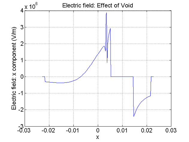
The horizontal component of the electric field plotted along the horizontal axis of symmetry. Image provided by: Peter A Wallace, Mohamed Alsharif, Donald M Hepburn, and Chengke Zhou, Glasgow Caledonian University.
As can be seen from the graph, the electric field is at zero when the void occurs. The sharp increase in the electric field at x = 0.003 m is a direct effect of the presence of the void.
Effects of Thermal and Electrical Stresses in Medium Voltage Cables
The first simulation, which measured thermal stress in the cable, shows the long-term response of a cable to an electrical load. the second model shows how defects in the cable can affect the electrical stress on the cable. These simulations can help researchers better understand the degradation induced in a medium voltage cable, and to predict when the cable needs to be replaced. In the future, the researchers will broaden their simulations to include thermally-induced mechanical stress, and then implement the hot, deformed model into further simulations. This will allow them to gain insight into the partial degradation due to electrostatic stresses in previously stressed cables.


Comments (1)
Gungor Kaya
January 13, 2020I created a blog post to list some important low voltage and mid voltage cable manufacturers, https://gungorkaya.com/en/supplier-companies/top-15-cable-manufacturers-from-turkey-in-2019/ . Similar lists on cables will be published in the future. This resource on comsol.com is helpful and I plan to show it a source on by posts for people who want to get informed more on the topic. Also Turkish Transformer Manufacturers are listed here.