
There are many ways to improve the frequency response of frequency-selective surfaces. However, optimizing these structures can require multiple steps. Every change to a design parameter — unit cell type, polarization, substrate properties, etc. — needs the expertise of simulation engineers. Simulation apps enable those with little or no simulation experience to run analyses for their specific stage of the design process on their own.
Tuning the Frequency Response of a Frequency-Selective Surface
In a previous blog post on frequency-selective surfaces (FSS), we introduced an example built with complementary split ring resonators, a popular unit cell choice for such structures. After an initial simulation analysis, it is likely that design engineers will want to modify the structure further to adjust its frequency response. They may want to alter the geometry of the current unit cell or maybe try a completely new unit cell type. Further, they might want to change the wave properties of the substrate, like the polarization or material properties.
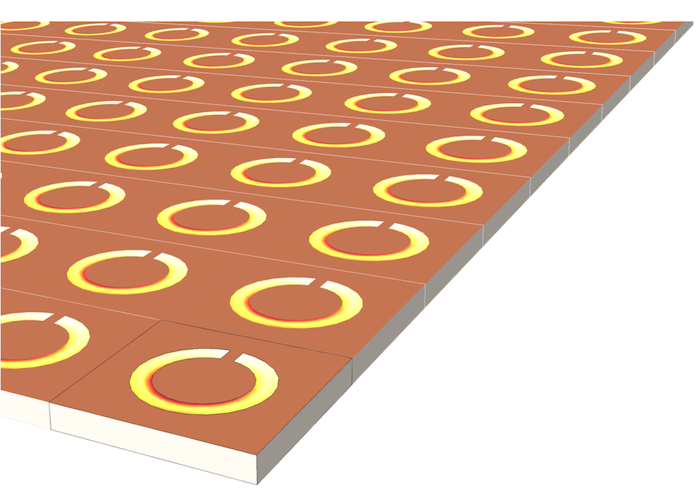
An FSS built with complementary split ring resonators.
As the list of design changes grows, it can create a bottleneck in the design process. The simulation expert must address these various requests as they come through, delivering simulation results in a timely manner. But with a simulation community that continues to grow and a workload that only becomes heavier, this can be rather difficult to accomplish.
Enter the Application Builder. With this tool, included in the COMSOL Multiphysics® software, simulation experts like you can design customized apps that others can use to modify design parameters and generate simulation results on their own. An app includes all of the physics of the underlying model to ensure the accuracy of results, but hides the complexity beneath an intuitive interface. Various elements can be added to these tools to guide users on how to set up and run simulations as well as how to communicate their findings.
Let’s take a look at an example FSS app.
Demo App: Frequency Selective Surface Simulator
As the creator of an app, you are in control of what end users can do. It’s up to you to decide which parameters can be modified based on the particular analysis. You can also decide how the different elements are displayed in the app’s layout.
In the Frequency Selective Surface Simulator example, the user interface (UI) is broken up into five different sections.
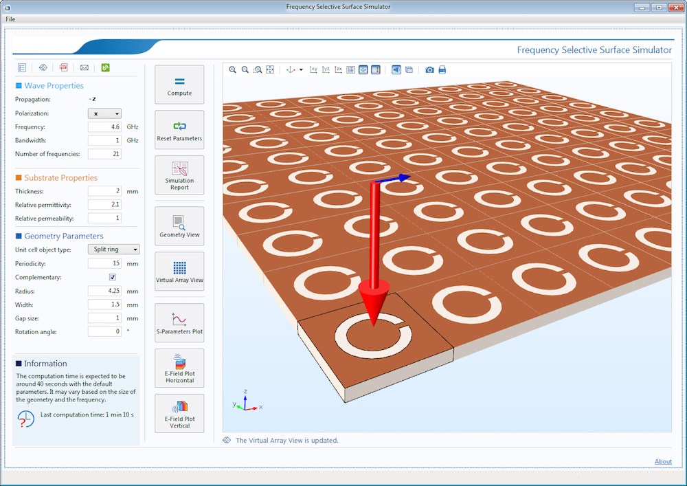
The UI of the Frequency Selective Surface Simulator.
In the toolbar, you can find five buttons, each of which offers shortcuts for performing various actions. The Properties button, which is selected by default, gives access to the user input fields for the wave and substrate settings. Clicking the Layout button provides information about the unit cell selected in the Geometry Parameters section. There are also options that enable users to easily access app documentation, email a simulation report, and read the COMSOL Blog via an embedded web browser.
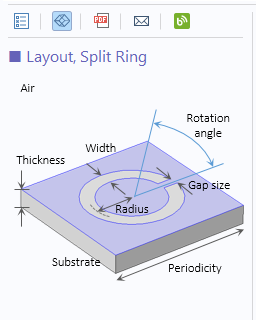
The layout information for the split ring cell type.
Shifting over to input parameters, notice that there are three sections, which we’ve already referenced above:
- Wave Properties
- Substrate Properties
- Geometry Parameters
The unit cell type can be selected from a combo box, where five popular FSS unit cell types are listed. Other built-in options include two predefined polarizations as well as propagation at normal incidence.
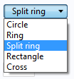
A combo box featuring the five unit cell types.
As an alternative to the Split ring option highlighted above, app users can choose to build a cross-strip FSS like that shown below. To make this change, they just need to select Cross from the combo box and uncheck the Complementary box in the Geometry Parameters section.
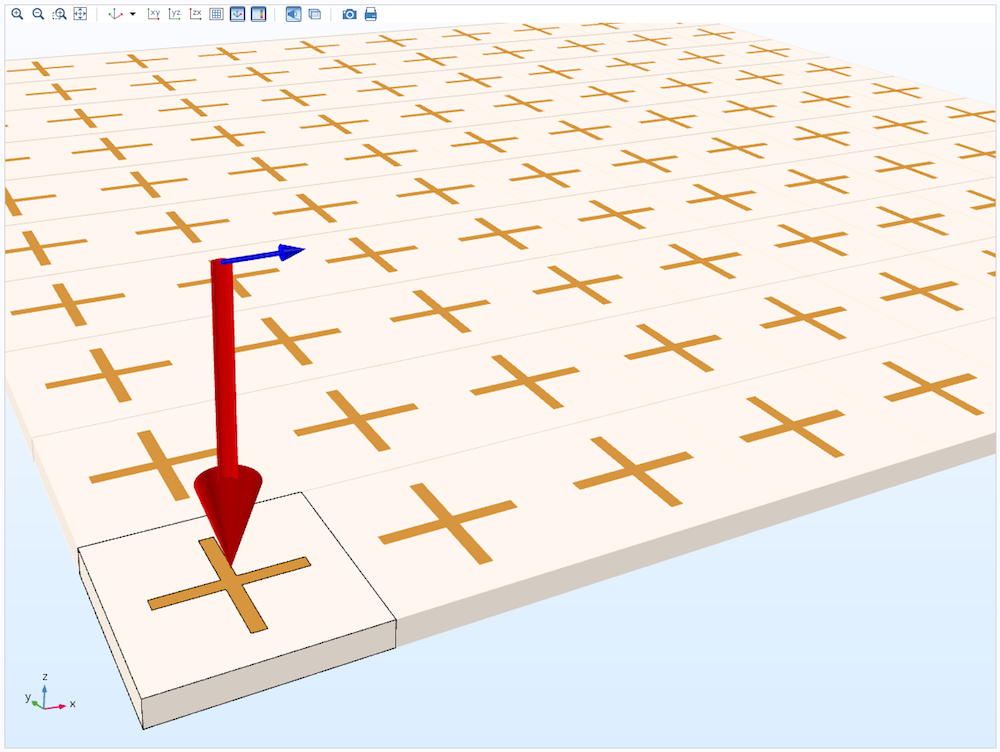
An example of a cross-strip FSS.
In the information section, three types of informative messages are displayed:
- Status when no solution is found
- Solution time for the most recent computation
- Warning that views and results haven’t been updated following a parameter change
These messages are useful for organizational purposes and keeping simulation analyses on track.
Like the toolbar, the command console is also home to a series of buttons (eight in total). After configuring input parameters, users can click the Geometry View or Virtual Array View buttons to visualize the updated geometry that reflects these modifications. Depending on the results they want to see in the Graphics window, they can choose from the S-Parameters Plot, E-field Plot Horizontal, or E-field Plot Vertical buttons. Additional options let users compute a simulation, reset parameters to their default values, and develop a simulation report.
When input parameters are modified, extra annotations appear on some of the buttons. The first is an orange exclamation mark. This signals that the geometry or virtual array view is invalid based on parameter changes. The sign disappears when users click one of the relative buttons to update the view with the most recent parameters.

The orange exclamation mark on the Geometry View button.
The second is a blue disabled sign. If an input parameter is modified after a simulation is run, the results don’t coincide with the current input parameters. Because the results aren’t up to date, they are disabled. To get rid of this sign, users can click Compute and run the app with the updated inputs.

The blue disabled sign on the S-Parameters Plot button.
Lastly, there is the Graphics window. Here, the geometry view, virtual array view, and various results plots can be displayed. This section also functions as a web browser, as demonstrated when the COMSOL Blog is selected via the toolbar.
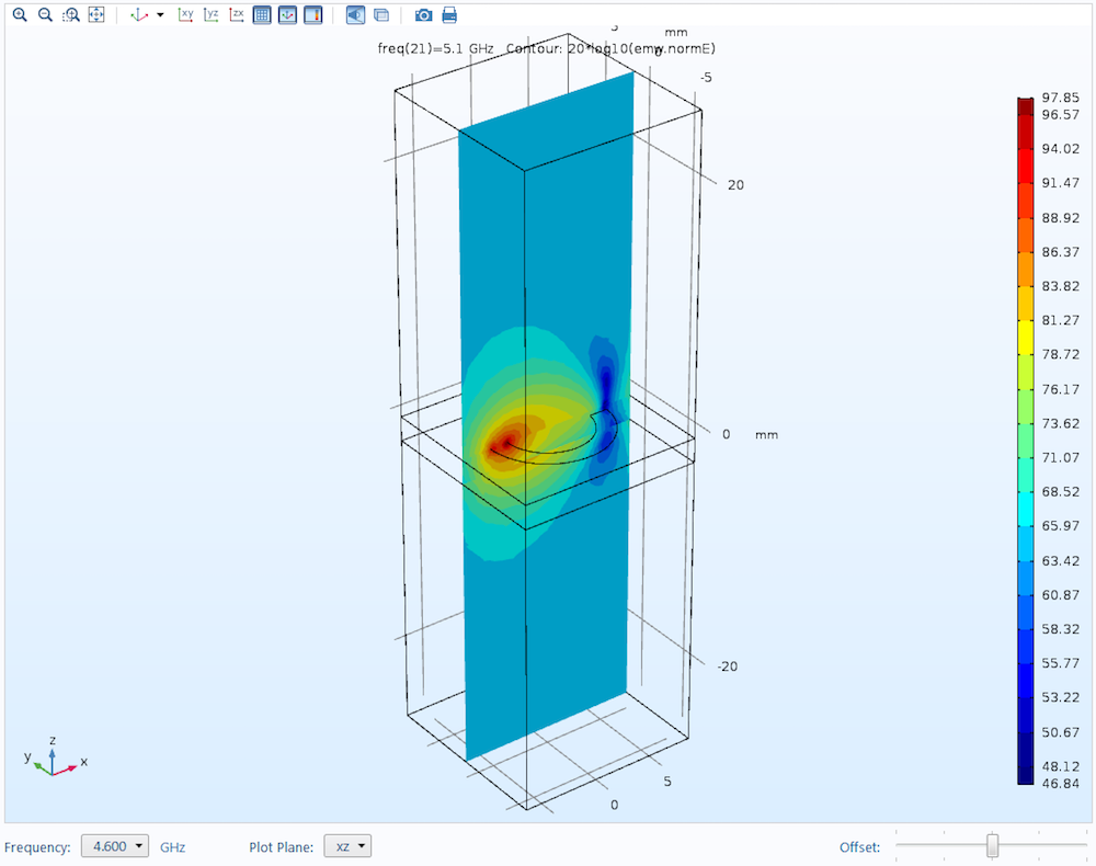
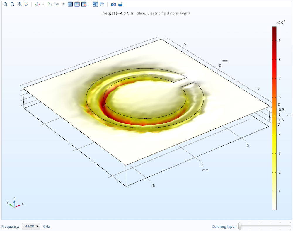
Various plots can be shown in the Graphics window. This includes vertical electric field norm plots (left), horizontal electric field norm plots (middle), and S-parameter plots (right).
Simulation Apps Enable a New Kind of Design Workflow
When you build a simulation app, you open up a world of possibilities for optimizing design workflows. With the ability to run their own simulations, design engineers can obtain results faster and use this information to advance their processes. They can then communicate these results to a larger audience in a format that is easy to understand. All the while, simulation experts can use the time that they would have spent running simulations over and over again to prioritize other projects in their queue.
Ready to start building apps of your own? Click the button above to try out the Frequency Selective Surface Simulator example.
Find More Examples of Apps Built from RF Models
- Check out other demo apps for designing RF applications:




Comments (0)