
Some structural applications involve thin or high aspect ratio structures sandwiched between other relatively low aspect ratio structures. For example, if a piezoelectric transducer is glued on the surface of a mechanical system, the thickness of the adhesive layer is very small in comparison to the two structures it glues together. Numerical modeling of such a thin layer in two or three dimensions requires resolving it with an appropriate finite element mesh. This can result in a large concentration of finite elements near the adhesive layer, leading to high computational cost and time. To avoid this issue, one common assumption many numerical simulations make is to assume perfect bonding between the two structures. By making this assumption, the numerical model ignores the effect of the flexibility of the adhesive layer. This will lead to inaccurate results because the adhesive layer is not infinitely stiff. In this blog post, we will show how to model such thin layers using COMSOL Multiphysics — without the need to draw the layer’s thickness explicitly, while still accounting for the effect of the thin elastic layer. This can lead to a more efficient structural analysis with significant reduction in computational cost and time, without sacrificing the accuracy of the simulation.
About the Thin Elastic Layer Boundary Condition
The Thin Elastic Layer boundary condition is suitable for modeling systems involving very thin elastic layers. This boundary condition has both elastic and damping properties and acts between two parts to model a thin elastic layer with specified stiffness and damping properties. On an interior boundary, the thin elastic layer decouples the displacements between two sides of the boundary. The two boundaries are then connected by elastic and viscous forces with equal size but opposite directions, proportional to the relative displacements and velocities. This means that you can replace any thin elastic layer in your geometry with just an interior surface with zero thickness, then use the Thin Elastic Layer boundary condition on the interior surface and assign it the properties of the elastic layer. You can include stiffness and damping values of the elastic layer. The Thin Elastic Layer boundary condition can be used in any type of analysis, including stationary, time dependent, frequency domain, and eigenfrequency.
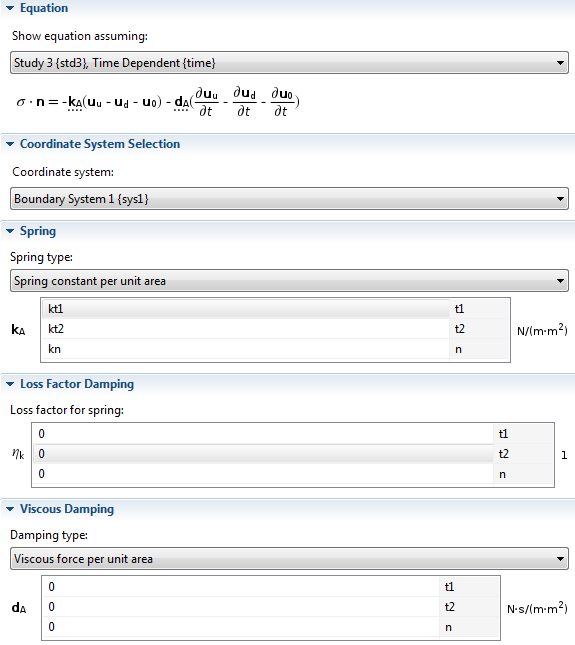
Thin Elastic Layer boundary condition settings.
Structural Analysis of a Composite Piezoelectric Transducer with an Adhesive Layer
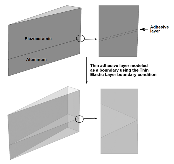
Next, let’s analyze an application that can benefit from the use of the Thin Elastic Layer boundary condition. Consider a composite piezoelectric transducer, for example. The composite piezoelectric transducer consists of piezoceramic, aluminum, and adhesive layers. The adhesive layer binds the piezoceramic and aluminum layers. In the simulation considered here, the length of the longest side of the adhesive layer is 27.5 mm and it can be 0.02 mm thick. Thus, the aspect ratio of the adhesive layer is quite high — it’s equal to 1.38 X 10³. The piezoceramic and aluminum layers have the same length for the longest side, but are far thicker, with values equal to 10 mm and 5 mm, respectively. An AC potential is applied on the electrode surfaces of both sides of the piezoceramic layer.
The objective of the following simulation is to find the first six eigenfrequencies of this composite piezoelectric transducer without explicitly drawing and meshing the thin adhesive layer. Instead we will consider its effect by using the Thin Elastic Layer boundary condition available in the MEMS, Structural Mechanics, and Acoustics Modules. This transducer model is taken from the Model Library of the MEMS Module where the adhesive is modeled explicitly for a thicker adhesive layer. The figure below shows that the geometry containing a very thin adhesive layer is replaced by a geometry with just an interior boundary, which is then assigned a Thin Elastic Layer boundary condition.
The Piezoelectric Device interface is used to simulate the composite structure. The boundary conditions consist of an applied potential and ground boundary conditions on both sides of the piezoceramic layer. The inner boundary representing the adhesive layer is assigned the Thin Elastic Layer boundary condition. Given the Young’s modulus (E), Poisson’s ratio (v), and the thickness (t) of the thin elastic layer, the spring constant per unit area in directions normal (kn) and tangential (kt) to the boundary can be estimated as: ![]() and
and ![]() , where G is the Shear modulus. Note the two asymptotes for kn: if v is low or closer to 0,
, where G is the Shear modulus. Note the two asymptotes for kn: if v is low or closer to 0, ![]() , and if v is high or closer to 0.5,
, and if v is high or closer to 0.5, ![]() , where K is the bulk modulus. The values of normal and tangential stiffness per unit area are used for spring constant per unit area in the Thin Elastic Layer boundary condition.
, where K is the bulk modulus. The values of normal and tangential stiffness per unit area are used for spring constant per unit area in the Thin Elastic Layer boundary condition.
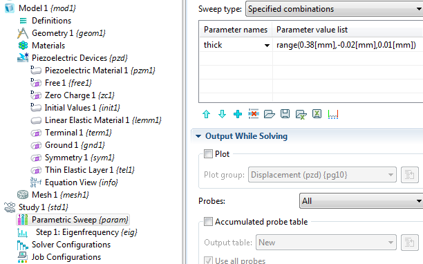
An eigenfrequency calculation is performed for values of the thickness of the adhesive layer ranging between 0.01 mm and 0.38 mm.
Results of our Structural Analysis
The following results show a comparison of six eigenfrequencies calculated using the Thin Elastic Layer boundary condition against the eigenfrequencies calculated by modeling the adhesive layer explicitly. The eigenfrequencies calculated using the Thin Elastic Layer boundary condition are indicated by an asterisk marker on solid lines, and the eigenfrequencies calculated by modeling the adhesive layer explicitly are indicated by dashed lines without any markers.
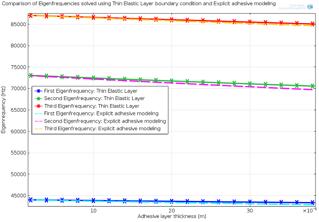
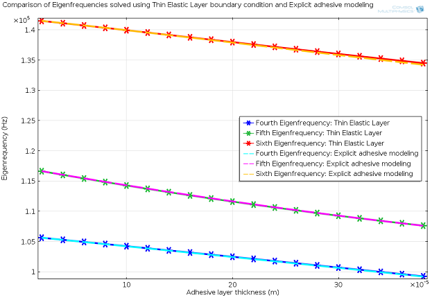
The above results show that for lower adhesive layer thickness values the solution obtained by using the Thin Elastic Layer boundary condition closely matches the solution obtained by modeling the adhesive explicitly. For large adhesive layer thickness values, the differences between the solution obtained from two calculations will increase with increased adhesive layer thickness. A sufficiently thick adhesive or elastic layer can be modeled explicitly. However, for very low values of the adhesive layer thickness or for simulating any thin elastic layer, the Thin Elastic Layer boundary condition is a more efficient way of modeling the effect of the thin layer without modeling the thin layer explicitly, while still accounting for its thickness and elastic properties.
There are several other important uses of the Thin Elastic Layer boundary condition. One such application is for large CAD models represented by a COMSOL Assembly, where the Thin Elastic Layer boundary condition can be used to approximate mechanical contact conditions for frequency-domain studies. Other uses, typically in combination with using a nonlinear stiffness, include modeling of fracture zones in geomechanics, simplified mechanical contact, and delamination of adhesive layers.


Comments (22)
George Joseph
April 10, 2014Hi,
I would like to know if I can use the thin elastic layer property to model compliant, ie. elastic electrodes for a capacitor. I should be able to specify the conductivity also.
Thank you
Chandan Kumar
April 11, 2014 COMSOL EmployeeDear George,
Thin elastic layer can be used for structural analysis of thin layers. Similar boundary conditions exist for other types of physics like, Distributed impedance in Electric currents physics or Distributed capacitance in Electrostatics physics. If you have further questions about the use of COMSOL in the analysis you are doing, please contact us by emailing your question to us at support@comsol.com.
Best regards,
Chandan
Andrew Melro
September 3, 2014Hi,
I was just wondering where the formulations for the spring constant per area came from? I would like to get some more understanding about how they are formulated
Thanks,
Andrew
Peter York
January 2, 2015Great post.
jpoday
April 11, 2015I’m also interested in the spring constant formulation. It seems as though it would be possible to simulate a pseudo-plasticity effect if they could be reformulated to be functions of extension.
Chandan Kumar
April 13, 2015 COMSOL EmployeeDear Andrew and Joseph,
There is no rigorous theoretical derivation for the spring constants that can be referenced here. The equations used are based on the asymptotic values explained in the article and its behavior for other Poisson’s ratio values.
Best regards,
Chandan
jpoday
April 24, 2015It seems as though it’s just Hooke’s Law in 3D. Then the strain terms are effectively replaced with the spring deformation divided by the thickness layer.
媛媛 于
January 24, 2017Hi, I really don’t know how to input the thickness of elastic layer, could you tell me? thank you very much.
Chandan Kumar
February 2, 2017 COMSOL EmployeeHi, the thickness of the elastic layer will be used to calculate the stiffness of the elastic layer. Please see the expressions for tangential and normal stiffness in the above blog.
Chandan Kumar
May 10, 2017 COMSOL EmployeePlease note that the calculation of spring stiffness values for thin elastic layer is now automated in COMSOL version 5.3. You only need to enter the Young’s modulus, poisson’s ratio and thickness of the layer.
Osman Sayginer
February 20, 2018Dear Chandan Kumar,
If you do a frequency domain analysis, how would you extract the displacement data on the Thin Elastic Layer?
Thank you
Chandan Kumar
February 20, 2018 COMSOL EmployeeDear Osman,
The up() and down() operators (for example: up(v) and down(v) where v is the y displacement) that are built-in for such boundary conditions will give you the displacement components of the boundaries on either side of the “spring layer” that the thin elastic layer represents. These operators are discussed here: https://www.comsol.com/blogs/analyze-thin-structures-using-up-and-down-operators/
Best regards,
Chandan
Osman Sayginer
February 21, 2018Dear Chandan,
Thank you for your response.
I think the model that you mentioned above is not the same model here: https://www.comsol.com/model/composite-piezoelectric-transducer >> I cannot see any Thin Elastic Layer in the model.
How do you choose the boundary as Thin Elastic Layer? When I try it, all boundaries looks “not applicable”.
Is there a reference model in structural mechanics model that I can check?
Thank you,
Best regards,
Osman
Chandan Kumar
February 21, 2018 COMSOL EmployeeDear Osman,
For all further questions on usage beyond the example shown here, please contact support@comsol.com
Best regards,
Chandan
Malisam Zhang
July 21, 2018we are manufacturers of producing electronic components,like piezo ceramics,ultrasonic transducer, may i know do you need it for your products ?
Here is our website :www.piezohannas.com
Xiangnan Pang
September 5, 2018Will the model using both Thin Elastic Layer and Added Mass be more close to the model with explicit adhesive modeling ? Cause Thin Elastic layer only accounts for the stiffness and damping effect and Added Mass accounts for the inertial effect of adhesive layer.
Anonymous
November 26, 2018Hi, I am using the elastic thin layer to simulate the deformation of fractures in geomechanics. The application of the initial in-situ stress will result in a reduction in the thickness of the elastic thin layer. But in fact, it is assumed that the elastic thin layer is in a mechanically stable state under the initial stress conditions, that is, the initial mechanical aperture of the elastic thin layer (or fracture) does not change unless the subsequent stress field changes. So how do I keep the initial thickness of the fracture constant? Is it by adding a pre-deformation sub-node? But it still doesn’t work. Can you give me some advice?
Brianne Costa
November 27, 2018 COMSOL EmployeeHello,
Thank you for your comment.
For questions related to your modeling, please contact our Support team.
Online Support Center: https://www.comsol.com/support
Email: support@comsol.com
Bat
April 19, 2019Hi,
I am actually working on a similar topic (calculating fracture aperture function of the stresses – in a 2D horizontal reservoir model).
I would be curious to know what was the answer to the post from
“Anonymous November 26, 2018 3:30 am
Hi, I am using the elastic thin layer to simulate the deformation of fractures in geomechanics. The application of the initial in-situ stress will result in a reduction in the thickness of the elastic thin layer. But in fact, it is assumed that the elastic thin layer is in a mechanically stable state under the initial stress conditions, that is, the initial mechanical aperture of the elastic thin layer (or fracture) does not change unless the subsequent stress field changes. So how do I keep the initial thickness of the fracture constant? Is it by adding a pre-deformation sub-node? But it still doesn’t work. Can you give me some advice?”
Thanks.
Chandan Kumar
April 19, 2019 COMSOL EmployeeDear Baptiste,
While the thin elastic layer was not meant for fracture deformation calculation, if you are using it for your purpose, you will want to contact support@comsol.com with your model file.
Best regards,
Chandan
Kim YoungKwang
September 6, 2024I want to download a problem (example) from the COMSOL homepage Application Gallery, what should I use as the filename or search? If you have a link, could you please share it with us?
Evan Sisler
December 12, 2024 COMSOL EmployeeHi Kim,
Thank you for your comment. You may find this tutorial model helpful:
https://www.comsol.com/model/composite-piezoelectric-transducer-503
For further questions on this topic, please contact our Support team using your COMSOL Access account at https://www.comsol.com/support.