After a pleasant day at the beach, you open your car door. It’s warm inside the vehicle, but it’s nothing a little air conditioning can’t fix. Then you sit down. The seat is burning hot, making for an uncomfortable ride home. Fortunately, there’s a way to avoid this scenario: Engineers can use thermoelectric devices that leverage the Seebeck and Peltier effects to control the temperature of car seats (among other applications).
2 Key Concepts in Themoelectricity: The Seebeck and Peltier Effects
Discovered in the early 1800s, the Seebeck and Peltier effects describe the relationship between temperature differences and electricity. The Seebeck effect was observed first: In 1821, German physicist Thomas Johann Seebeck found that when he formed a circuit by joining two different metals, heating one junction generated electricity. He later learned that simply holding a junction in his hand created enough of a temperature difference to produce a current.
About 13 years later, Jean Peltier, a French watchmaker and physicist who experimented with electrodynamics, realized that electricity likewise leads to temperature differences; i.e., the Peltier effect. Building on Seebeck’s work, Peltier found that by simply changing the direction of a current, he could achieve either heating or cooling at a junction of two conductors joined at two points, with the heat moving from one point to the other.
Cooling and Heating Devices via Thermoelectricity
Thermoelectric devices, which rely on the Peltier and Seebeck effects, are used for a wide range of cooling and heating applications, including:
- Refrigeration
- Laser cooling
- Cryotherapy
- Powering satellites
- Climate control in buildings
- Car seat heating and cooling

With thermoelectric cooling, a ventilated car seat can project cool air to the surface of the seat while removing hot (waste) air.
A crucial component of thermoelectric cooler and heater designs is the thermoelectric leg. Two of these legs can form a thermocouple, which helps a device provide more precise temperature control via the Seebeck effect. In this type of setup, each leg (conductor) is composed of a different semiconductor material — one p-type and the other n-type — and the legs connect at a junction.

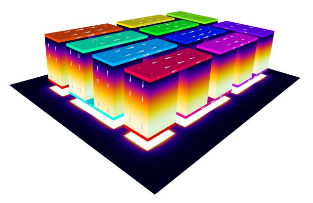
Simulation of a thermoelectric cooler.
Using the COMSOL Multiphysics® software and add-on Heat Transfer Module, you can evaluate the design of a thermoelectric leg and observe the Peltier and Seebeck effects. Note that while the following benchmark model only accounts for the Peltier effect, it’s also possible to simulate the Seebeck effect, as demonstrated by this thermoelectric generator tutorial.
Modeling Thermoelectric Devices in the COMSOL® Software
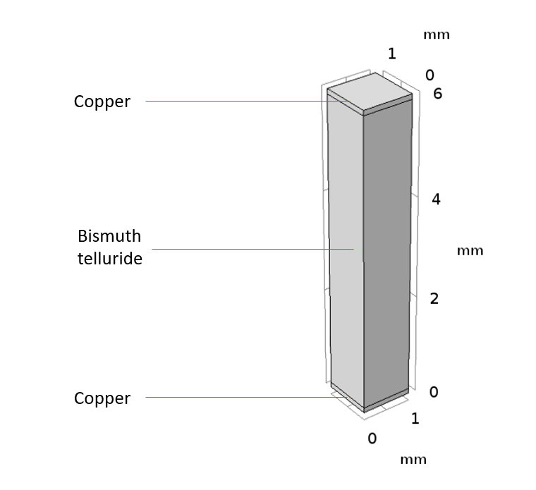
In this example, the thermoelectric leg is 1 by 1 by 6 mm. As shown below, the middle part of the leg is made of a bismuth telluride metal capped by two copper electrodes that are 0.1 m thick.

Thermoelectric leg geometry.
While the material properties for the leg are available in the thermoelectric material library in the Heat Transfer Module, the model takes the properties of bismuth telluride from experimental data (Reference 1 in the model documentation) so that the results can be validated. The same experimental data is also used to define the Seebeck coefficient for copper.
As for the temperature setup, the top copper electrode and lateral surfaces are thermally insulated, while the bottom surface is held at a steady 0°C. In addition, the bottom electrode is grounded at 0 V. The total inward current through the top electrode is 0.7 A.
Evaluating the Simulation Results
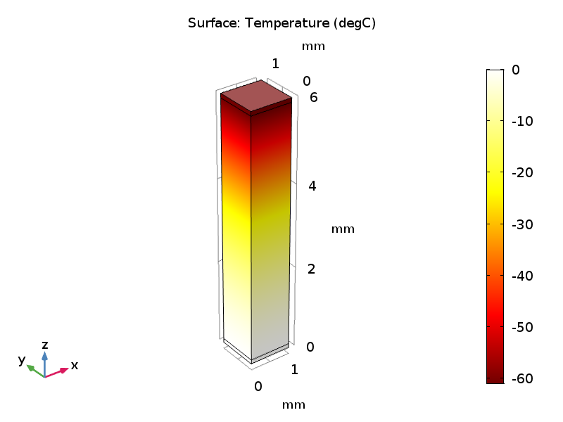
The first result shows the cooling effect (i.e., the Peltier effect) caused by the current circulating in the thermoelectric device. Below, you can see that the surface temperature of the leg steadily decreases from the top electrode once the current reaches the bismuth material. This temperature field is comparable with the validated results from published research.

Temperature field for the surface of the thermoelectric leg.
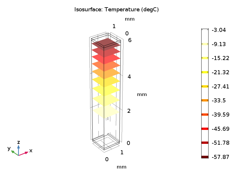
Next, you can see the isothermal surfaces and heat flux of the leg. As shown below, they correspond with the direction of the electric current, going from top to bottom.

Isothermal surfaces in the thermoelectric leg.
Finally, you can see the electrode potential in the leg. Because of how the inward current density is set on the boundary, the top-level electrode reaches an electric potential of approximately 49.1 mV. This value correlates well with the reference data.

Electrode potential in the thermoelectric leg.
The results for the thermoelectric leg model are in good agreement with the experimental data and simulation results that have been published in literature, demonstrating the capability of the COMSOL® software to accurately model thermoelectric devices.
Next Steps
Try the thermoelectric leg model for yourself: Click the button below, which will take you to the Application Gallery. From there, you can download a step-by-step guide and the MPH file.
Related Resources
- Simulate the Seebeck effect using the same model with different boundary conditions: Try the Thermoelectric Generator tutorial model
- Read this blog post on analyzing thermoelectric cooler designs using apps


Comments (4)
Shahvaiz Khan
December 24, 2020You wrote current’s value is 0.7A. Can you explain me how did you get that?
Shruti Verma
July 3, 2023from where did the current value come?
Joshua Tristancho
June 29, 2024Related post https://www.forosdeelectronica.com/threads/celda-peltier-casera.146311/#post-1484327
Ram Thakur
January 7, 2026thank you for the opportunity. we are working on thermoelectric cement composites, seeking thermal conductivity , electrical conductivity and seebeck coefficient of cement and cement filled graphene for low grade waste heat to power nanodevices. Kindly suggest any suitable method for the same. best regards