
Today, we are pleased to introduce a new guest author, Vincent Bruyere of SIMTEC, who shares insight into the modeling of induction furnaces.
Induction heating has become an important process in many applications, from cooking meals to manufacturing. It is valued for its precision and efficiency along with being a non-contact form of heating. In this guest post, I will describe how to build an induction furnace model in COMSOL Multiphysics and demonstrate how it can enhance your design.
The Principles Behind Induction Heating
The physical principles that govern the process of induction heating are quite simple: An alternating current flows in a solenoid (coil), which generates a transient magnetic field. Following Maxwell’s equations, this magnetic field induces electric currents (eddy currents) in nearby conductor materials. If the application is a furnace and due to the Joule effect, heat is generated and the melting point of the charge (metal) can be reached. By adjusting the current parameters, the molten metal can be maintained as a liquid or its solidification can be precisely controlled.
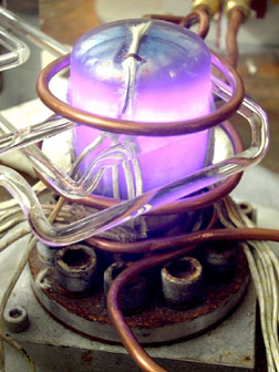
Induction heating. (In the public domain, via Wikimedia Commons).
Modeling with COMSOL Multiphysics
When building the model, we begin by describing the geometry and the associated materials. As is often the case for such industrial applications, an axisymmetric assumption can be considered. The chosen geometry (shown in the figure below) is composed of the classical components of an induction furnace: the crucible that contains the charge (metal), a thermal screen that controls the heat radiation, and a water-cooled coil in which the electrical power is applied.
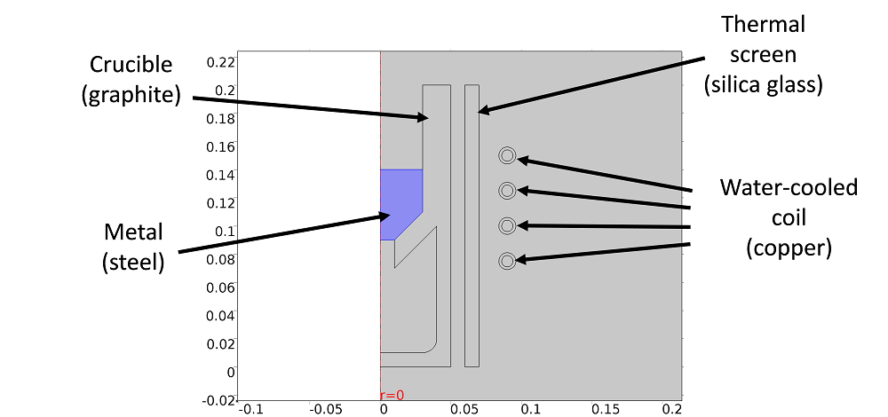
The model’s geometry.
By using the Induction Heating multiphysics interface, two physic interfaces — Magnetic Field and Heat Transfer in Solids — are automatically added to the component. The multiphysics couplings add the electromagnetic power dissipation as a heat source, while the electromagnetic material properties can depend on the temperature. A strong coupling is then ensured by applying the preselected study step, which can be the Frequency-Stationary or the Frequency-Transient study. In these cases, Ampere’s law is solved for each time step for a given frequency, and then the thermal problem is solved for a transient or stationary state.
The Electromagnetic Problem
Through considering the axisymmetric assumption, only the component of the magnetic vector potential that is perpendicular to the geometry plane (A\Phi) is non-zero. In order to apply boundary conditions, we can assume that a state of magnetic insulation is apparent quite a “far” distance from the furnace. It is important to ensure that this state of insulation is far enough away to guarantee that it does not affect the solution. An efficient technique is to use the Infinite Elements domain, available in the Definition item of the component. This method allows you to limit the size of the problem by applying a coordinate scaling to a layer of virtual domains surrounding the physical region of interest.
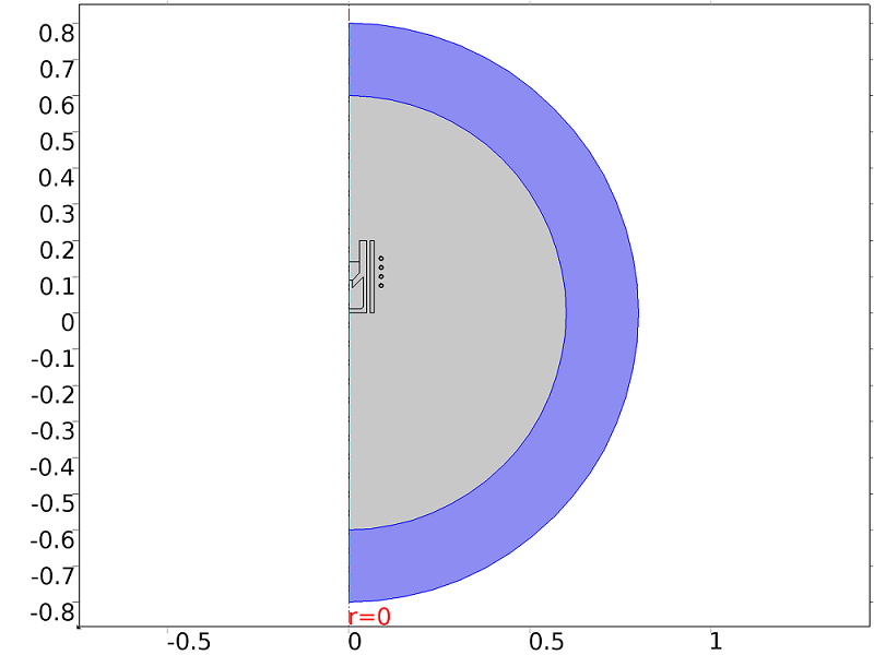
The Infinite Elements domain.
To apply the electromagnetic source, different methods are available. The selected method depends on the type of geometry and how well the electric properties are known. In our case, the geometry of the coil is truly represented (by four turns), and a Single-Turn Coil condition is thus added to these copper surfaces.
Concerning our knowledge of the coil excitation, we consider a case where the coil power is known. To apply this quantity to the entire coil, the Coil Group mode has to be activated to ensure that the voltage used to compute the global coil power is the sum of the voltages of all the turns. By using this kind of excitation, the problem becomes nonlinear, and COMSOL Multiphysics automatically adds the related equations to compute the correct power (see here).
The Thermal Problem
The heat equation is solved for only the solid parts by neglecting the effect of the surrounding air. Indeed, heat is essentially transferred by radiation in this problem. Therefore, the Surface-to-Surface Radiation boundary condition is added to the Heat Transfer in Solids physics interface by selecting the external boundaries of each component.
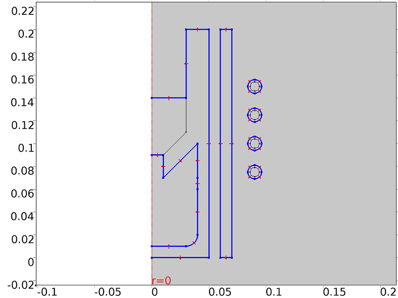
Surface-to-surface radiation boundaries.
A circulation of water is classically used in industrial furnaces for cooling the coil. The design of the coil enables this channel flow by using a circular hollow section (see the geometry of the coil in the next figure). A convective volume loss term is then added to each turn by considering the mass flow rate \dot{m} and the heat capacity of water C_p, the inlet temperature of water T_{in}, and the internal radius of the coil r_{int}:
Numerical Aspects
For each computation, an important parameter has to be quantified: the skin depth, as most of the electric current will flow through this skin depth. This parameter is dependent on the vacuum permeability, \mu_0, the relative permeability of the material, \mu_R, the electrical conductivity, \sigma, and the frequency f by the following formula:
The higher the frequency, the thinner the skin depth. Consequently, by modulating the current frequency, the location of the heat source can be precisely controlled. Numerically, it means that for each conductor material, the mesh has to be sufficiently fine to ensure precision. Convention requires that at least four elements cover this area. This can be easily achieved by using the Boundary Layers mesh type, as illustrated here:
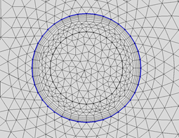
The Boundary Layers mesh type for the external coil boundaries. The figure also shows the inner tube where cooling water flows.
The model can now be solved by specifying the frequency in the study step. In our case, a frequency of 1000 Hz is used and a stationary solution is obtained in less than a minute with a laptop.
Electromagnetic and Thermal Results
The magnitude (norm) of the resulting current density is plotted in the following figure, together with the magnetic field fluxlines. We can see that the maximum current density is located in the coil domains. The distribution of the current density is not uniform throughout the coil section and the current tends to flow in the inner part of the turns. In the charge (metal), the magnetic field fluxlines are highly deformed and an eddy current flowing in the opposite direction is induced.
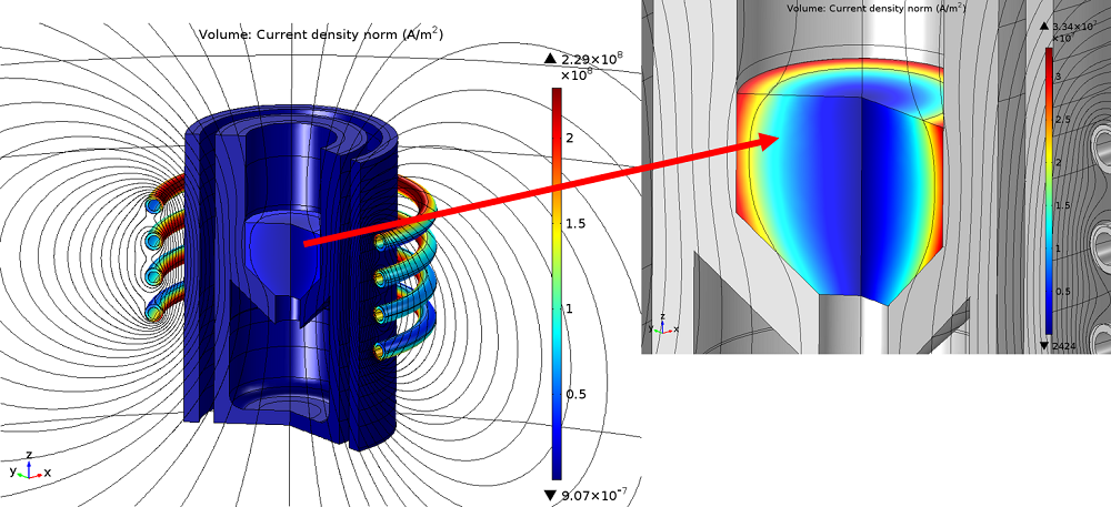
Global and local plots of the current density norm.
As it flows into the resistive charge, this current dissipates energy in the material. The resulting temperature in each part of the furnace is highlighted below. We can observe that, even if the current is very intense in the coil, the temperature is close to ambient thanks to the water cooling system. On the contrary, the temperature in the charge is high and close to the melting point of the material due to eddy currents and the Joule effect. The other parts of the furnace are heated by radiation.
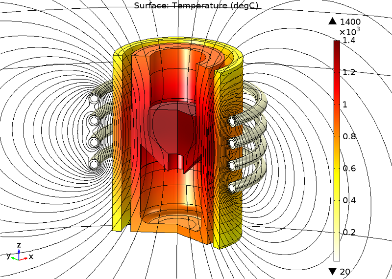
A model illustrating the temperature distribution in the furnace.
The furnace geometry can now be customized according to different design constraints. The coil characteristics (frequency, power, type of geometry, number of turns, etc.) and the geometry of all the parts can now be optimized to reduce the energy consumption and ensure a controlled melting of the material.
How Does the Electromagnetic Field Affect the Melted Pool Behavior?
To take things a step further and understand how the melted metal behaves in the furnace, hydrodynamics equations can easily be added to the model. By considering a homogeneous temperature of the melted pool, surface tension and buoyancy effects can be neglected, with only the Lorentz forces remaining. An additional source term is then added to the fluid momentum equation, with j representing the current density and B representing the magnetic flux density:
Both vectors are complex entities and were previously obtained for a given frequency. The time-averaged Lorentz force contribution, given in COMSOL Multiphysics by the “mf.FLtzavr” and “mf.FLtzavz” parameters, must be used. Through neglecting the effect of the fluid on the magnetic field, the hydraulic problem can then be solved in an uncoupled way.
The image below shows the melted metal behavior at a stationary state. Two typical recirculation zones are generated in the fluid. Stirring can be controlled by adapting the frequency or the power of the current. This can have both positive and negative effects. On the one hand, it is a way to improve the homogeneity of the bath. On the other hand, stirring may lead to a rapid erosion of the refractory walls. As for the heating phase, and depending on the design constraints, parametric studies can now be computed to improve the process.
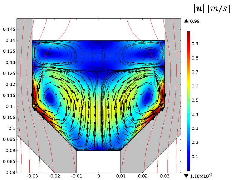
Velocity vectors in the melted pool.
About the Guest Author
Vincent Bruyere received his PhD in mechanical engineering from the National Institute of Applied Science (Lyon), with a research topic related to lubricated contacts. Following a post-doctoral position at the Atomic Energy and Alternative Energies Commission (CEA), Bruyere now works at SIMTEC as a modeling engineer. He develops numerical models applied predominantly to fluid dynamics as well as to thermal and electromagnetic applications.


Comments (8)
Sam Lobanov
June 12, 2016Where this model can be found for downloading?
Arifur Rahaman
July 7, 2017Where this model can be found for downloading?
Bridget Cunningham
July 7, 2017 COMSOL EmployeeHello Sam and Arifur,
Thank you both for your comments.
While this specific model file is not available for download, we encourage you to browse our Application Gallery for tutorial examples: https://www.comsol.com/models.
Dolores Gomez
October 30, 2018Hello,
It would be possible to obtain the .mph files corresponding to this simulation?
Thanks in advance.
Dolores
erez beer
December 31, 2019hi Vincent,
I am finding your model very intresting. good job!
I have build an induction heating model also and now i am trying to get force calculations/ is there are any diffrences between liquid metal an solid in the way the model solving EM and Lorentz forces?
i have tryed to find your comsol file at the web/ comsol site.
maybe i can use it to lern more?
thanks for any answe
erez beer
erez beer
January 1, 2020Hi vincent
My name is EREZ and i wrote to you erlier today asking from you some assitent in IH model.
I think i forgot to leave my email.
erezbeer@gmail.com
thank you
erez
Media Marius
August 19, 2021Dear Mr.,
I have to make the numerical model in Comsol, for the device consisting of susceptor – crucible – uranium bar. This device is located inside the vacuum enclosure, and inductor is placed outside the vacuum enclosure.
I need your model “Modeling of Furnace”, for:
– exact settings of predefined frequency transient, induction heating, electromagnetic heating mode in the heat transfer module;
– For crucible heating at 1800 degC, I have the voltage of the coil maxim 250 V, frequency is 10 kHz. With this parameters (voltage, freq.) cannot obtain (from model heating simulation) 1800 degC in crucible.
Or, I can send you my model to make the correct settings.
We can collaborate to carry out a research paper. (marius.media@upit.ro)
King regards
zack ivs
May 8, 2023I would like to ask a question in a simulation of induction welding of two 1 mm thick copper tubes using coils. Despite a magnetic flux density (phi) of 20e6A/m² and surface intégration on the 2D axes symmetric, the volumetric power density in the simulation is low (0.0019 W). Can anyone help me understand the reasons for this low power density and examine the simulation results and the freq=50hz? Thank you.