
To accurately simulate a gear and obtain useful results, it is important to consider a number of elements behind the device’s design and how they are modeled. New features and functionality in the COMSOL Multiphysics® software provide you with the tools to address such properties and thus advance the reliability of your simulation studies. Today, we’ll review the various elements of gear modeling and explain how to account for them in our modeling processes.
A Brief Overview of Gears
As a refresher, let’s begin by reviewing some of the key concepts behind modeling gears in COMSOL Multiphysics. A gear is defined in a Gear node as a rigid body with six degrees of freedom in the form of translations and rotations at the center of rotation. It is used in a Gear Pair node in the model tree in order to connect with another gear. Here, you can specify a finite stiffness for the gear mesh or gear tooth, either for individual gears or for the pair. A mathematical formulation is used to describe the connection between two gears, without any need for a defined, realistic gear geometry to detect the contact between the two gears. Therefore, you can represent a gear with either a realistic gear geometry or any similar geometry of a disc.
It is possible to compute the inertial properties of a gear from the geometry using its calculated mass density, or you can directly enter the properties in the form of mass and moment of inertia in the node’s edit fields. You can also apply external forces and moments on the gear as well as constrain certain degrees of freedom of a gear. For instance, when modeling torsional vibrations, all of the degrees of freedom except the axial rotation can be constrained.
Selecting a Gear Type
COMSOL Multiphysics offers a number of standard gear types, each with its own merit and applications. As mentioned above, the gear is an abstract object, but if you want to add a realistic geometry for visualization, you can access the Part Libraries, where you can find various types of gears and racks.
In the following images, you can see the various types of gears and racks available and the geometrical parameters needed for their mathematical descriptions.
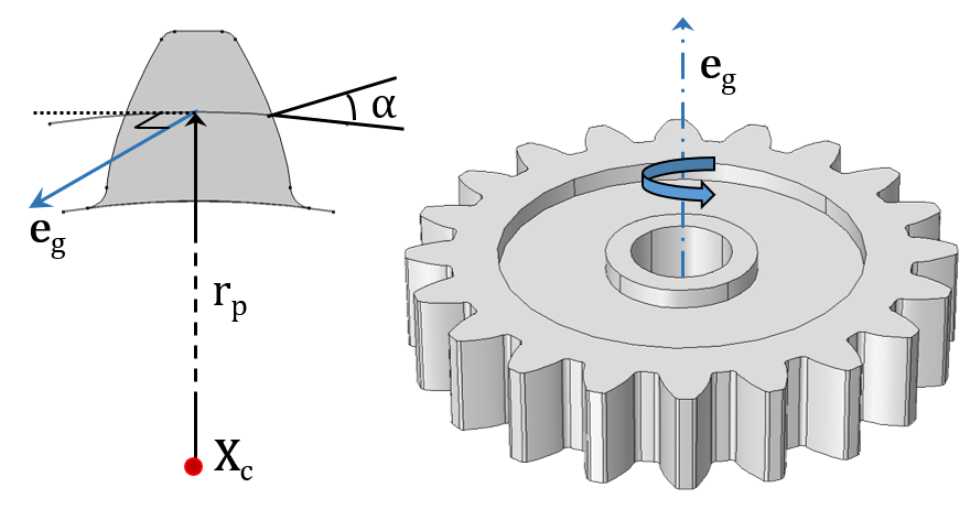
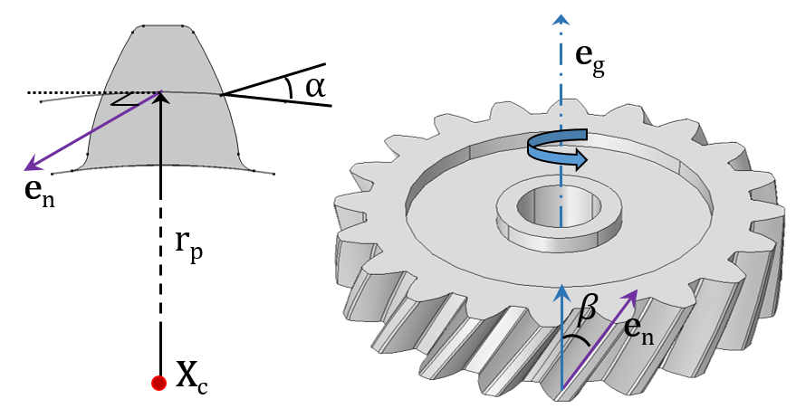
A Spur Gear (left) and Helical Gear (right) with their external gear mesh.
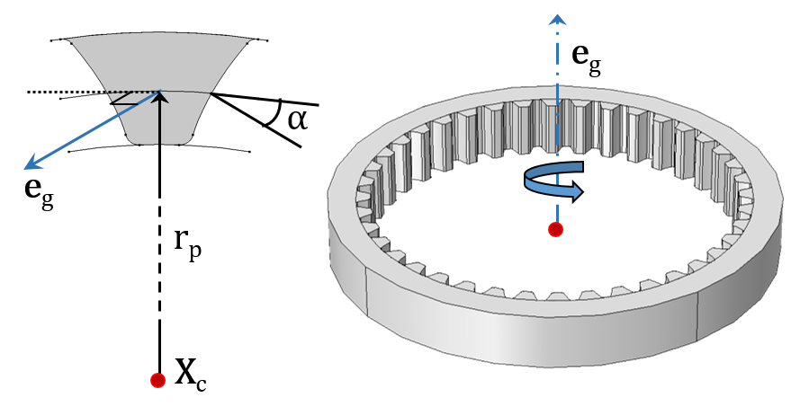
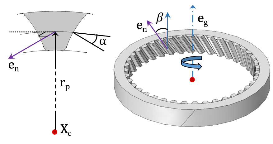
A Spur Gear (left) and Helical Gear (right) with their internal gear mesh.
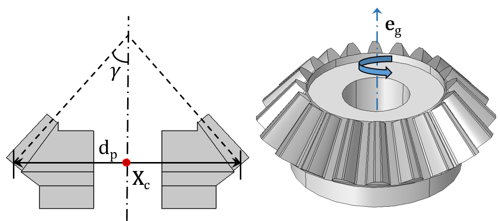
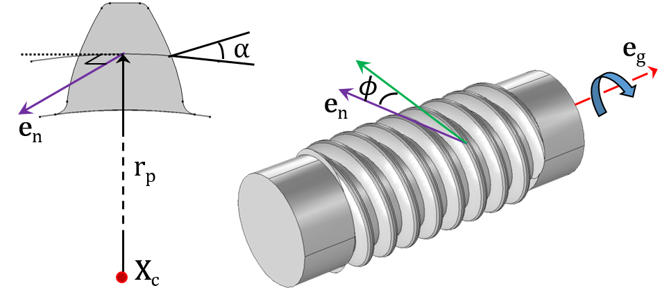
A Bevel Gear (left) and Worm Gear (right).
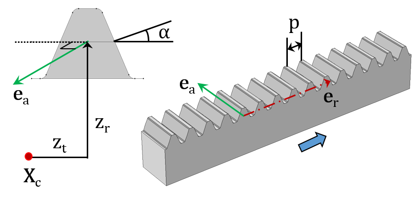
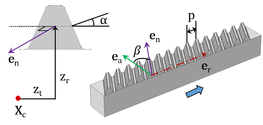
A Spur Rack (left) and Helical Rack (right).
The inputs required to model each gear type are shown in the respective figures. They are as follows:
- Center of rotation (Xc)
- Gear axis (eg) and rack axis (er)
- Pitch radius (rp) and pitch diameter (dp)
- Pressure angle (α), helix angle (β), cone angle (γ), and lead angle (Φ)
- Transverse pitch (p)
- Tangential offset (zt) and radial offset (zr)
Defining Gear Tooth Parameters
After selecting the appropriate gear type, you can then define the parameters controlling the size and shape of the gear teeth. As an example, these parameters are required to define a helical gear:
- Number of teeth
- Pitch diameter
- Pressure angle
- Helix angle

A screenshot showing the settings window for a helical gear. Various inputs required to model a helical gear, including gear properties, gear axis, center of rotation, and density are shown.
Specifying Gear Position and Orientation
The next step is to define the position and orientation of the gear. The gear position is defined in terms of the center of rotation. This is the point at which the degrees of freedom are created and the rotation is interpreted. The forces and moments acting on the gear due to meshing with other gears are also interpreted about this point. By default, the center of rotation is set to the center of mass of the gear, but there are other ways to define it explicitly as well.
The gear orientation is specified in terms of the gear axis, which is the axis of rotation passing through the center of rotation. The gear axis is used when creating the gear local coordinate system. Also interpreted about this axis is the gear rotation, a degree of freedom in the Gear Pair node.
Mounting a Gear on a Shaft
You can mount gears in one of two ways: on a flexible or a rigid shaft. These devices can be mounted either rigidly or with a finite stiffness using a fixed joint. Joints are the features used to connect two components by allowing certain relative motion between them.
When there is no clearance between the gear and the shaft in the geometry, the objects can be either in an assembly state or a union state. For a flexible shaft, gears are by default rigidly mounted on the shaft if both the gear and shaft are in a union state.
It is not necessary to model a shaft in order to mount gears, as the devices can be mounted directly to the ‘ground’ either rigidly or with a finite stiffness using a hinge joint. The prescribed displacement/rotation subnode of a gear can also be used for this purpose.
Note that it is also possible to support shafts on:
- Flexible housing
- Rigid housing
- Ground
This can be done using hinge joints, which can be rigid or have a finite stiffness.
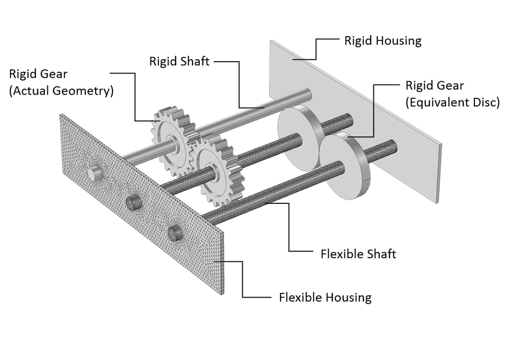
Figure showing gears with an actual geometry as well as those modeled through equivalent discs. Different mounting methods for gears and shafts are also depicted.
Connecting Two Gears
In order to connect the different types of gears that you have defined in your model, you can use a Gear Pair node. This node can connect spur, helical, and bevel gears. You can also use Worm and Wheel as well as Rack and Pinion nodes for their specific cases. These nodes connect two gears in such a way that there is no relative motion along the line of action at the contact point. The remaining displacements and rotations of the two gears are independent of each other.
Each Gear Pair node adds two degrees of freedom:
- Wheel rotation about the gear axis
- Pinion rotation about the gear axis
The following constraints are added by the Gear Pair node in order to connect two gears:
- Rotation constraint: This establishes the connection between the wheel and pinion rotation using the gear ratio. The gear ratio is defined as the ratio of angular velocities of the wheel and pinion, and it can also be obtained by taking the ratio of the number of teeth of the pinion and the wheel. The effects of gear elasticity, transmission error, and backlash are also included in the constraint.
- Contact point constraint: This ensures that there is no relative motion at the contact point along the line of action.
- Unique triad constraint: This ensures that the coordinate systems of both gears are still unique and well defined. It is particularly useful for planetary gears.
For a line contact model, one more constraint is added to restrict the relative rotation about a line joining the two gear centers. If friction is included, frictional forces are obtained using the contact force, which is computed as the reaction force of the contact point constraint. These frictional forces are then applied on both gears in a plane perpendicular to the line of action.
Compatibility Criteria for Proper Tooth Meshing
In a Gear Pair node, you can select any two gears defined in the model. But in order to achieve proper tooth meshing, a set of gears must fulfill the following compatibility criteria:
- Normal module of both gears must be the same
- Pressure angle of both gears must be the same
- For parallel-axis helical gears, the sum of the helix angles must be zero
- For crossed-axis helical gears, the sum of the helix angles must be nonzero
All these checks are automatically performed and an error message is issued during equation compilation if the two selected gears are not compatible.
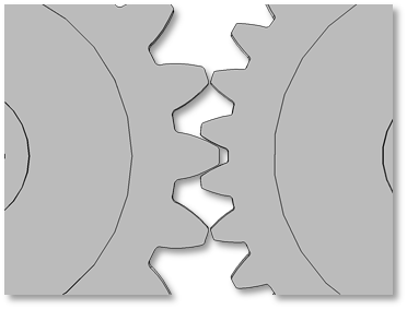
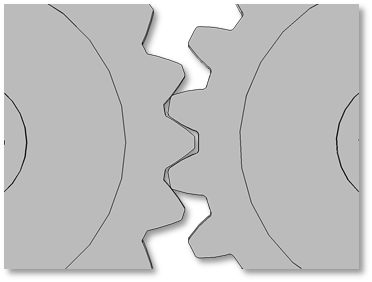
Examples of incompatible gear mesh. In the figure on the left, the gears have different modules. In the figure on the right, the gears have different pressure angles.
Defining a Gear Coordinate System
A coordinate system for each gear is defined using the gear axis and center of rotation of both gears. The first axis of the coordinate system triad is the gear axis itself. The second axis is the direction pointing from the center of rotation to the contact point. The third axis is normal to the plane containing the first two axes. This coordinate system is attached to the gear and varies with the changes in gear orientation. Note, however, that it does not rotate with the gear rotation about its own axis.
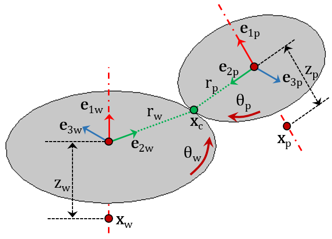
A schematic showing coordinate systems and other parameters for both gears connected by a gear pair.
These quantities are illustrated in the above figure of a gear pair:
- Coordinate system of wheel ({e1w, e2w, e3w}) and pinion ({e1p, e2p, e3p})
- Center of rotation of wheel (Xw) and pinion (Xp)
- Pitch radius of wheel (rw) and pinion (rp)
- Axial offset of wheel (zw) and pinion (zp)
- Rotation of wheel (θw) and pinion (θp) about their respective axes
Gear Tooth Coordinate System and Line of Action
The gear tooth coordinate system is defined for both gears by rotating the gear coordinate system with the tooth angle matrix. This matrix is constructed using the helix angle and the cone angle.
The line of action, meanwhile, is defined as the normal direction of the gear tooth surface at the contact point on the pitch circle. This is the direction along which the forces are transferred from one gear to another. It is defined by rotating the third axis of the gear tooth coordinate system (gear tangent) about the first axis of the gear tooth coordinate system with the pressure angle (α). Based on the direction of the driver gear, the gear tangent can be rotated either clockwise or counterclockwise.
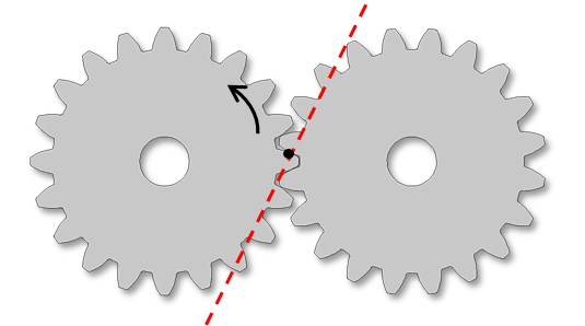
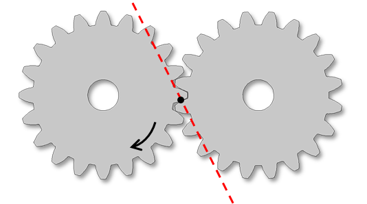
Two figures depicting the line of action and the direction of rotation of the driver gear. The line of action is defined due to the fact that the driver gear and tangent rotate in the clockwise direction (left) and counterclockwise direction (right).
Gear Contact Models
The contact between the two gears is modeled through analytically founded equations. These are independent of the finite element mesh and thus much faster and more robust compared to mesh-based contact methods. To compute contact forces and moments, you can choose one of two methods:
- Using a weak-form constraint: In this method, the contact point constraint is implemented in the weak form and the Lagrange multiplier of this constraint is the contact force. This method is accurate, but it uses an extra variable for the Lagrange multiplier and requires proper scaling in order to have good convergence.
- Using a penalty method: Here, the constraint is implemented using the penalty method and the penalty force represents the contact force. This method does not require any additional variables, but an appropriate value for the penalty factor must be selected.
The point of contact on each gear is defined via the center of rotation, displacement vector at the center of rotation, contact point offset from the gear center, pitch radius, and cone angle. Based on the orientation of both gears, different gear pairs can be classified into one of two configurations:
- Parallel or intersecting (i.e., spur gears, helical gears, and bevel gears)
- Neither parallel nor intersecting (i.e., crossed helical gears and worm gears)
For a parallel or intersecting configuration, the contact point offset from the pinion center is the input and the contact point offset from the wheel center is automatically computed. The contact model can be selected as either:
- Point contact, which is suitable for thin gears
- Line contact, which is suitable for thick gears
For a configuration that is neither parallel nor intersecting, the contact point offset from the pinion, as well as the wheel center, is automatically computed. The reason for this is that there is always a point contact and the contact point can be uniquely determined.

From left to right: Thin gears (point contact model), thick gears (line contact model), and thick gears with an axial offset.
Examples of Different Gear Pairs
Now that we’ve explored gears in further detail and how to connect them, let’s look at various examples of gear pairs classified based on their configurations. You can use many gear pairs together in order to model complex parallel and planetary gear trains.
Some examples of the parallel axis configuration are as follows:
- External spur gears
- External helical gears (parallel)
- Internal spur gears
- Internal helical gears (parallel)
Bevel gears, meanwhile, offer an example of an intersecting axis configuration.
Set of spur gears and parallel helical gears with an external gear meshƒ.
Set of spur gears, one with an internal gear mesh and the other with an external gear mesh, as well as a set of bevel gears.
Some examples of a crossed (neither parallel nor intersecting) axis configuration are as follows:
- External helical gears (crossed)
- Worm and wheel
Set of crossed helical gears with an external gear mesh and the worm and wheel.
Rack and pinion with a straight gear mesh.
Understanding and Addressing Important Elements of Gear Modeling
When it comes to modeling gears, there are many important elements to consider to optimize your simulation results. As we’ve demonstrated here today, the new features and functionality for gear modeling in COMSOL Multiphysics allow you to address such elements, providing you with more useful insight into how to improve your gear design.
In the next blog post in our Gear Modeling series, we’ll discuss how you can use advanced features on your gear pairs (i.e., gear mesh elasticity, backlash, transmission error, and friction) in order to perform simulations requiring greater fidelity. We’ll also show you how these parameters affect the dynamics of your system. Stay tuned!


Comments (0)