
In the course of building multiphysics models, we often encounter situations in which the solution to one physics is periodic — or very nearly so — while the solutions to other physics of interest are nonperiodic. If we know this ahead of time, it is possible to exploit the periodicity to reduce computational requirements. Here, we will demonstrate how to accomplish this using the General Extrusion component couplings in COMSOL Multiphysics.
This is the first blog post in a two-part series. Read Part 2 here.
Exploiting Periodicity in the Multiphysics Modeling of a Microfluidic Device
Let’s begin by looking at a microfluidic device, as shown below. Such devices feature small channels that are filled with fluids carrying different chemical species. Within their design, a common goal is to achieve optimal mixing within a small surface area, hence the serpentine channel.
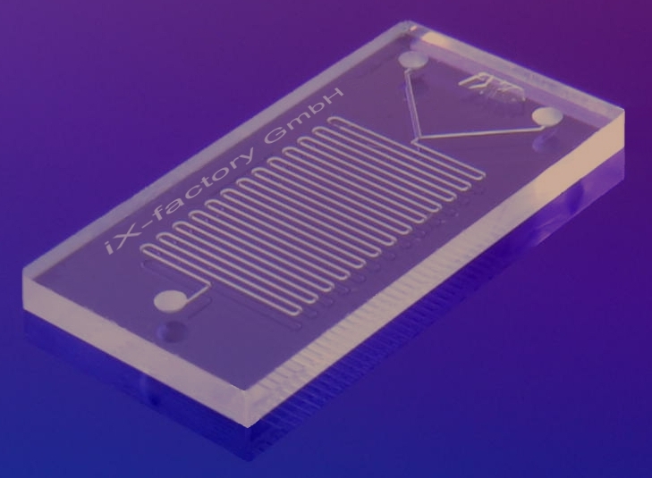
A typical microfluidic device. Image by IX-factory STK — Own work, via Wikimedia Commons.
The schematic below illustrates that there are two fluid inlets, both of which carry the same solvent (water) but a different solute. At the outlet, we want the species to be well mixed. To model such a situation, we want to solve the Navier-Stokes equations for the flow. This computed flow field can then be used as input for the convection-diffusion equation governing the species concentration. The Micromixer tutorial, available in our Application Gallery, is an example of such a model.
Now, if desired, it is possible to model the entire device shown above. However, if we neglect the structure near the inlet and the outlet, we can reasonably assume that the flow within the channel bends will be identical between the unit cells. Therefore, we can greatly reduce our model by solving only for the fluid flow within one unit cell and patterning this flow solution throughout the modeling domain for the convection-diffusion problem.
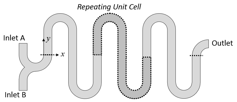
Schematic of a microfluidic mixer that depicts the repeated unit cell and the inlet and outlet zones.
For such a unit cell model, the walls of the channels are set to the Wall, No Slip condition. The Periodic Flow condition is used to set the velocity so it is identical at the inlet and outlet boundaries, allowing us to specify a pressure drop over a single unit cell. A pressure constraint at a single point is used to gauge fix the pressure field. The working fluid is water with properties defined at room temperature and pressure. The flow solution on this unit cell is also plotted, as shown below.
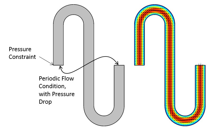
The periodic modeling domain and the fluid flow solution.
Now that we have the solution on one unit cell, we can use the General Extrusion component coupling to map the solution from this one unit cell onto the repeated domains. This will enable us to define the flow field in the entire serpentine section.
Using General Extrusion Component Couplings to Pattern and Reuse the Solution
The General Extrusion feature is available in the model tree under Component > Definitions > Component Coupling. The settings for this feature are illustrated below. To map the solution from one domain into the other domains that are offset by a known displacement along the x-axis, the destination map uses the expression “x-Disp” for the x-expression. Thus, every point in the original domain is mapped along the positive x-direction by the specified displacement. Since there is no displacement in the y-direction, the y-expression is set at its default “y”.
The variable Disp is individually defined within each of the three domains, as shown in the figure below. Therefore, only a single operator is needed to map the velocity field into all of the domains. Within the original domain, a displacement of zero is used.
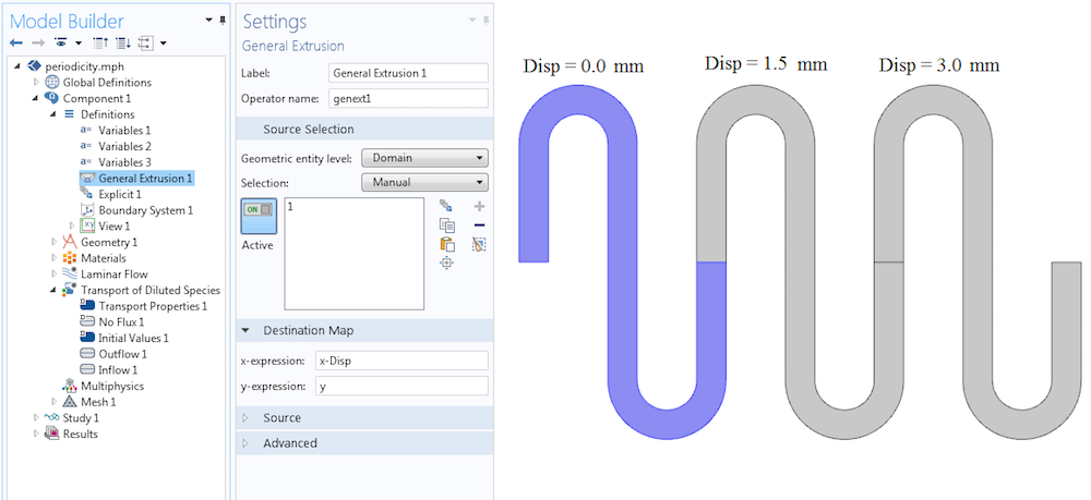
The settings for the General Extrusion operator and the definitions of the variable in the three domains.
With the General Extrusion operator defined, we can now use it throughout the model. In this example, the operator is used by the Transport of Diluted Species interface to define the velocity field (illustrated below). The velocity field is given by u and v, the fluid velocity in the x– and y-directions, respectively. The components of this velocity field are now defined in all of the repeated domains via the General Extrusion operator: genext1(u) and genext1(v), respectively.
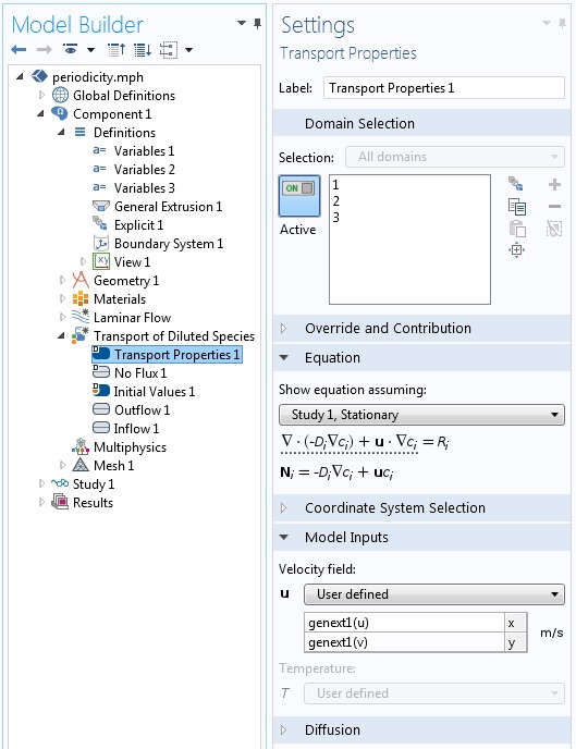
The General Extrusion operator is used to define the velocity field in all three periodic domains.
Now that the velocity field is defined throughout the modeling domain, the species concentration at the inlet is defined via the Inflow boundary condition. This applies a varying species concentration over the inlet boundary. An Outlet boundary condition is applied at the other end.
Although it is not strictly necessary to do so, the mesh is copied from the one domain used to solve for the fluid flow to all of the other domains. The Copy Domain mesh feature can copy the mesh exactly, thereby avoiding any interpolation of the flow solution between meshes.
The model is solved in two steps — first, the Laminar Flow physics interface is solved, and then the Transport of Diluted Species interface is solved. This is reasonable to do since it is assumed that the flow field is independent of the species concentration. The results of the analysis, including the concentration and the mapped velocity field, are depicted below.
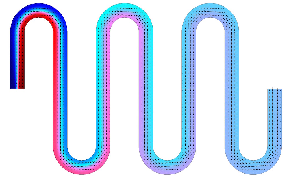
The species concentration (shown in color) is solved in all three repeating domains. The periodic velocity field, indicated by the arrows, is solved in one domain and mapped into the others.
Closing Remarks
We have discussed how the General Extrusion component coupling can be used to set up a linear pattern of a periodic solution as part of a multiphysics analysis. For circular periodicity, a rotation matrix, not a linear shift, must be used in the destination map. An example of defining such a rotation matrix is detailed in this previous blog post.
The approach we have applied here is appropriate for any instance in which a spatially repeating solution needs to be utilized by other physics. Where might you use it in your multiphysics modeling?


Comments (7)
sultan
November 25, 2019Thank you for your Blog. It is really a helpful example. I have only one small question, if you don’t mind, you could maybe write the expressions of the variable ”disp”.
Thank you for your time
Walter Frei
December 2, 2019 COMSOL EmployeeDisp is defined as one of three different scalars (0,1.5,3 mm) as per the fourth figure.
sultan
April 11, 2020thank you very much
Oluwaseyi Ayeni
February 27, 2022Thank you Walter for a wonderful discussion. I am trying to implement the Periodic Boundary condition in a 3D model by following your post but I have some questions. First, did you only the repeating unit in your graphics window before using the General Extrusion and Periodic Boundary conditions node or was it the entire geometry? Second, I used the defined the Variable “Disp” three times as in the images above but with different values (with increments in the periodic direction specified) while the destination map setting had as input “z-Disp” as suggested above but I got the error “Error in multiphysics compilation.” “Duplicate parameter/variable name. – Variable: comp1.Disp”. Please can you explain what I am doing wrong? Thank you.
Walter Frei
February 28, 2022 COMSOL EmployeeHello Oluwaseyi, This sounds like a case of a variable name used twice, but you may want to reach out to the support team for help.
Oluwaseyi Ayeni
February 28, 2022Okay, thanks I will.
Tanmay Khare
February 14, 2024Hi Walter,
This was a really helpful article. Would you be able to provide us with the COMSOL files for setting up this simulation? I would like to use it to follow through as I try to use a similar method for setting up repeating units in my simulation.
Thank you!