When you think of a valve, what is the first thing that comes to mind? Electromagnetic waves, or perhaps, Stokes flow separating charged chemicals in a microchannel system? Maybe neither. The truth is, when researchers try to separate small (in the picoliters region), well-defined sample volumes of chemicals, the dispensing accuracy provided by a mechanical regulator probably won’t suffice. An electrokinetic valve, a type of microfluidic valve, on the other hand, provides the perfect solution by giving researchers the flow control needed for accurate measurements during selected chemical and biological analyses.
How an Electrokinetic Valve Works
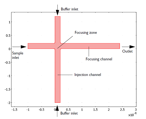
Electrokinetic valves are commonly found in applications where controlled transport of a charged sample ion is desired. For instance, it’s often found in biochips or when performing an electrophoretic analysis. The geometry of this micro-device typically constitutes two perpendicular channels — the focusing channel and the injection channel. The intersection zone between the two channels is called the focusing zone. Additionally, there are two stages that describe the operation of this device: the focusing stage and the injection stage. First, during the focusing stage, a pressure-driven creeping flow (Stokes flow) containing the sample ion is introduced at one side of the focusing channel, while another pressure-driven creeping flow of buffering solution is simultaneously introduced from both ends of the injection channel. These two solutions meet at the focusing zone before exiting at the outlet side of the focusing channel, as illustrated below.

Electrokinetic valve layout during the focusing stage. During the injection stage, the lower buffer inlet becomes the injection outlet.
Once the sample fluid has entered the focusing zone, the device switches over to the second stage, the injection stage. This means that the pressure-driven flow is turned off and an electric field is immediately applied along both of the channels. This applied field drives the dissociated sample ions in the focusing zone at right angles to the focusing channel and through the injection channel, ensuring a clean separation of the sample ions.
However, to achieve a properly working electrokinetic valve, the user must calibrate the pressure-induced creeping flow as well as the electric potential applied along the channels. Digitally simulating such a system is a crucial part of the calibration process, as it allows researchers to determine the voltage applied during the injection stage and the initial velocity induced during the focusing stage.
Video: How to Model a Microfluidic Valve
By leveraging the ability of COMSOL Multiphysics to draw previously computed solutions from different study steps, you can create a model that uses solutions from the focusing stage as initial conditions for the injection stage. Using the same feature, you can also save computation time by creating a stationary study for the electric field and using its solutions to analyze the time-dependent transport of diluted species in the injection stage. Furthermore, you can quantitatively plot the species concentration as a result of the applied electric current during the different time steps. You can use the results to help decide whether or not the distribution of the concentration along the channel is appropriate for your purpose.
We have created a video series for you so you can see how to do just that. The first video shows the focusing stage, while the second describes the injection stage.
In the second video below, two modes are analyzed (mode A and mode B), differing only by the placement of the applied electric field. Mode B is exemplified as the appropriate scenario fitting the valve’s purpose as its distribution is more normal, compared with mode A.
Creeping Behind the Scenes of a Microfluidic Valve
The induced creeping flow in the microfluidic valve occurs when the Reynolds number for a flow is very low (Re«1). This means that the fluid’s viscous forces dominate over the advective inertial forces. Therefore, during this flow, we neglect the inertial term of the Navier-Stokes equations, so that it is described by the Stokes equations. This single-phase flow occurs not only during flows with high viscosity, but also when the flow length-scales are small, thus making it ideal for the purpose of this particular microfluidics model, even though the solvent is water.

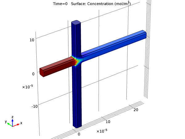
Focusing stage steady-state solution using induced creeping flow. This solution is also the initial solution (t = 0) for the time-dependent injection stage.
The Transport of Diluted Species Interface
The Transport of Diluted Species interface in this model accounts for the transport of the species in the buffering solution, during both the focusing and injection stages. This model assumes the chemical species to be transported through migration and convection with the diffusion coefficient set to zero. The mass balance equation is consequently only spatially-dependent on the velocity field, of which solutions are obtained from the creeping flow solver for the momentum balance term during the focusing stage. During the injection stage, the mass balance also becomes dependent on the electric field, adding terms that are dependent on Faraday’s constant, the electric potential, the charge number of the ionic species, and the ionic mobility. The unspecified ionic mobility is then related for each instance to the species diffusivity through the molar gas constant and temperature by the Nernst-Einstein relationship.
Further Reading
- Download the Electrokinetic Valve model used in the video
- Chemical Reaction Engineering Module
- Microfluidics Module


Comments (0)