COMSOL Multiphysics version 5.0 introduced users to an improved “Numeric TEM port” feature for transmission lines. This feature includes enhanced functionality, utilizing the techniques behind the calculation of impedance in 2D models and applying them in 3D instances.
From 2D to 3D: Finding Impedance
When studying the behavior of transmission lines, the characteristic impedance is often analyzed. The characteristic impedance refers to the ratio between the voltage and the current of a wave that propagates along the transmission line. By calculating this impedance, designers can modify the transmission line to improve its power transfer and reduce signal reflection.
The Model Gallery features examples of finding impedance in transmission line structures. Two types highlighted are the coaxial cable and the parallel-wire transmission line.
In each of these models, the transmission line operates in TEM mode, with the electric and magnetic fields normal to the propagation’s direction along the cable. Because of this, modeling a 2D cross section is enough to calculate the fields and impedance, and the models are solved with a Mode Analysis study feature. For both cases, the voltage is analyzed as a line integral of the electric field that exists between conductors. Meanwhile, the current is obtained as a line integral of the magnetic field along either conductor’s boundary or any closed contour that cuts the space between the conductors into two parts.
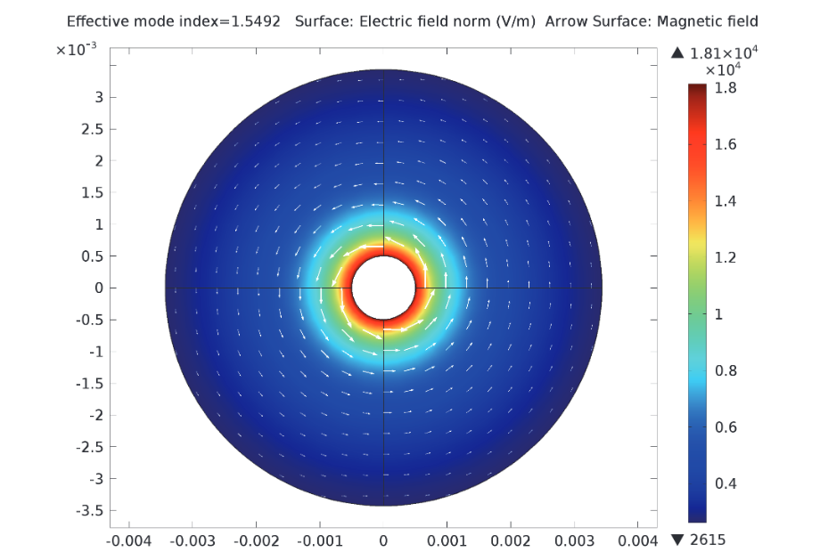
In these arrow plots, the surface represents the electric field magnitude and the arrows represent the magnetic field magnitude. The image on the left shows the fields inside a coaxial cable and the image on the right shows the fields around two parallel wires.
The problem-solving technique used to calculate the impedance in these 2D models has now been extended into the 3D realm with the Numeric TEM port feature. With the addition of settings and subfeatures in COMSOL Multiphysics version 5.0, this feature can now be used to find the impedance in 3D models.
An Example of Using Numeric TEM Ports
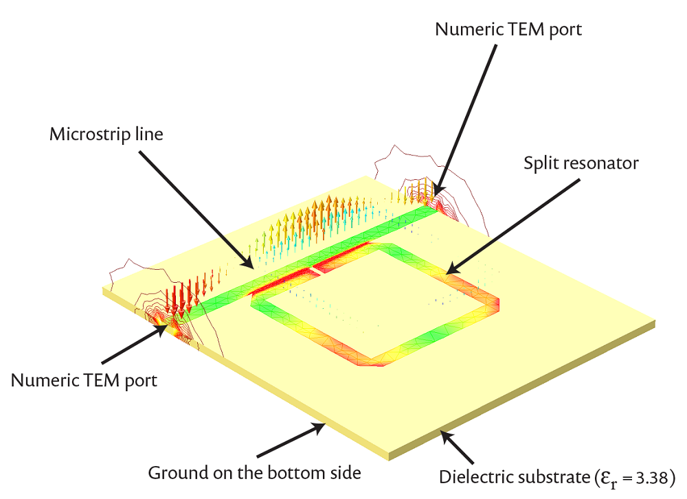
The Notch Filter Using a Split Ring Resonator model provides an introduction on how to use the Numeric TEM ports. This model consists of a split ring resonator that is coupled to a microstrip line. The circuit as a whole acts as a notch, or band-stop, filter.

A schematic of the circuit.
To realize a band-stop filter response, the resonator’s split part is bordering and coupled to the microstrip line. The printed split ring resonator, which is on a ground plane, features a number of resonant modes. In this case, we are interested in the frequency near 2.4 GHz. The metal parts of the model are treated as perfect electric conductors and scattering boundary conditions are used on the model domain’s exterior boundaries, with the exception of the ground plane. The remainder is treated as a vacuum domain.
A numeric port is added on each surface of the ends of the microstrip line. These ports are designed to calculate the electric mode field on the structure, which is accomplished through a Boundary Mode Analysis. “Analyzed as a TEM field” is selected within the numeric port setting. This setting requires that the electric and magnetic field integration lines are defined in order to calculate the port’s voltage and current. The information from these integration lines is then used to find the port characteristic impedance.
The ratio of the calculated impedance and the reference impedance is used to scale the port mode field. The electric fields are led between two conductors and the field component in the propagation’s direction, with the normal to the port boundary negligible. Thus, the port mode can be analyzed as a transverse electromagnetic, or TEM, field.
In the first figure below, the electric field norm is illustrated on the xy-plane. This plot shows the symmetrical confinement of the electric fields along the split ring resonator at the frequency of interest (2.4 GHz).

A model of the electric field norm highlights the electric fields’ symmetrical confinement along the split ring resonator at 2.4 GHz.
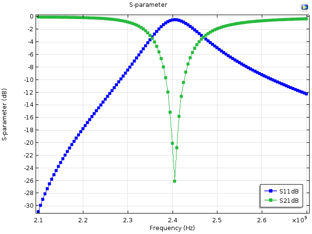
The next plot illustrates the device’s frequency response. We can observe that the device behaves as a band-stop filter, as around 2.4 GHz, its S11 is nearly 0 dB and its S21 is less than -10 dB.

A plot of the device’s frequency response illustrates that the device does act as an efficient band-stop filter.


Comments (4)
Junlong Kou
October 10, 2017Hi, Bridget, Thanks for the explanation. I have one question on the sentence “The ratio of the calculated impedance and the reference impedance is used to scale the port mode field.” What does this mean? Is this used to enable the impedance of the port to become the same as the reference impedance? But, the characteristic impedance of the port is determined by the 2D port geometry and materials used. Please help to understand this.
Jiyoun Munn
October 13, 2017 COMSOL EmployeeThe port mode field is scaled to address the impedance mismatch between the calculated characteristic impedance and reference impedance.
Naeem Riaz
May 10, 2018Hi,
what if this structure is over the surface and are of metal, lets say copper. what should we change to get results ?
I mean that if the strip and the rectangle is on top of the substrate and,
substrate = insulator
rest of structure is of metal.
Please advise.
Thanks
Thomas Jung
July 14, 2018“This setting requires that the electric and magnetic field integration lines are defined in order to calculate the port’s voltage and current.”
Where in the COMSOL menu is there the option to define the field integration lines? HFSS allows you to draw a line between two points. COMSOL’s approach is not clear.