
Nonisothermal flow combines CFD and heat transfer analysis. In cases where the temperature of the fluid at an inlet is a known quantity, a Temperature boundary condition can be used. However, there are some important situations where this is not the case, and an Inflow boundary condition can improve the model accuracy and reduce the computational cost of the simulation. Here, we review how this more sophisticated thermal boundary condition can be set at a flow inlet.
Simulating Heat Transfer with the Inflow Boundary Condition
The important boundary condition that we will discuss here is called the Inflow boundary condition. It is available at boundaries that are exterior to a fluid domain and is equivalent to having a virtual channel “upstream”. The Inflow boundary condition is used to define a heat flux at the inlet boundary that brings the same energy to the fluid domain as if you had modeled the virtual channel as a real CFD domain. The virtual channel can be seen as a long insulated channel with given thermal properties at the inlet, and with the same velocity profile as defined in the settings for the Inflow boundary condition.
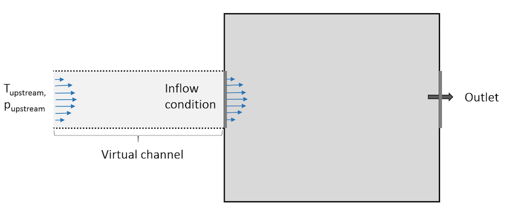
Representation of the virtual domain corresponding to an Inflow boundary condition.
From a mathematical point of view, the boundary condition is formulated as a flux condition:
(1)
where the enthalpy variation \Delta H is defined as:
(2)
where we can designate the two terms:
and
so that we can write:
This expression contains two terms. The first, {\Delta H}_T, depends on the temperature difference while the second, {\Delta H}_p, depends on the pressure difference.
Eq. (1) expresses the fact that the normal conductive heat flux (-\mathbf{n} \cdot \mathbf{q}= k\nabla T \cdot \bf{n}) at the inflow boundary is proportional to the flow rate and enthalpy variation between the upstream conditions and inlet conditions.
Temperature Contribution to the Inflow Boundary Condition
As shown in Eq. (2), the enthalpy variation depends in general both on the difference in temperature and in pressure. However, the pressure contribution to the enthalpy, {\Delta H}_p, is neglected when the work due to pressure changes is not included in the energy equation.
In the COMSOL Multiphysics® software, this is controlled in the Nonisothermal Flow multiphysics feature using the corresponding check box:

There is another classical case where this term cancels out: when the fluid is modeled as an ideal gas. Indeed, in this case, \alpha_p = \frac{1}{T}.
First, let’s assume that the pressure contribution to the enthalpy is null. (We have seen above that this is actually quite often the case.) Then, the boundary condition reads:
(3)
When advective heat transfer dominates at the inlet (large flow rates), the temperature gradient, and hence the heat transfer by conduction, in the normal direction to the inlet boundary is very small. So in this case, Eq. (3) imposes that the enthalpy variation is close to zero. As C_p is positive, the Inflow boundary condition requires T = T_{\mathrm{upstream}} to be fulfilled. So, when advective heat transfer dominates at the inlet, the Inflow boundary condition is almost equivalent to a Dirichlet boundary condition that prescribes the upstream temperature at the inlet.
Conversely, when the flow rate is low or in the presence of large heat sources or sinks next to the inlet, the conductive heat flux cannot be neglected. In addition, the inlet temperature has to be adjusted to balance the energy brought by the flow at the inlet and the energy transferred by conduction from the interior, as described by Eq. (3).
This makes it possible to observe a realistic upstream feedback due to thermal conduction from the inlet surroundings.
Comparing the Inflow and Danckwerts Boundary Conditions
Keeping the assumption that the enthalpy only depends on the temperature and that, in addition, the heat capacity is constant, Eq. (1) reads:
(4)
which corresponds to a Danckwerts boundary condition that is used in, for example, the Transport of Diluted Species interface.
In practice, there are many models where the heat capacity is nearly constant, so the Inflow boundary condition behaves like a Danckwerts boundary condition with an averaged heat capacity. Interestingly, if this is not the case, the Inflow boundary condition automatically accounts for an incoming flux that corresponds to the enthalpy and cannot be expressed by simply using a Danckwerts boundary condition.
Pressure Contribution to the Inflow Boundary Condition
Let’s discuss a general case. In Eq. (2), the enthalpy variation depends both on the difference in temperature and in pressure.
Considering that the Inflow boundary condition models a virtual channel feeding the inlet, we expect pressure losses between the virtual channel inlet and the boundary where the condition is defined. This explains why the upstream pressure is different from the inlet pressure. While the fluid flows through the channel, it is subject to pressure work that results in a temperature change between the virtual channel inlet and the boundary where the Inflow boundary condition is defined. This is what is described by the pressure-dependent term in Eq. (2). Note that the viscous dissipation in the virtual channel is not accounted for.
In practical situations, the pressure contribution, {\Delta H}_p, is often zero (for ideal gases or when work done by pressure changes are neglected) or small in the sense that a very small difference between the upstream temperature and the inflow temperature is enough to balance it. To illustrate this, consider two common fluids:
- Air: Its density is defined from the ideal gas law in the Material Library, hence the pressure contribution to the enthalpy, {\Delta H}_p, is zero.
- Water: The order of magnitude of C_p is 1000 J/K/kg while the order of magnitude of \frac{1-\alpha_p T}{\rho} is 0.001 m3/kg. A pressure difference of 1 bar (= 105 Pa) and a temperature difference of 0.1 K induce {\Delta H}_T \sim 0.1 \mathrm{K} \times 1000 \mathrm{J/K/kg} = 100 \mathrm{J/kg} and {\Delta H}_p \sim 0.001\mathrm{m^3/kg} \times 10^5\mathrm{Pa} = 100\mathrm{J/kg}, respectively; two contributions with the same order of magnitude in \Delta H.
Comparing the Inflow and Temperature Boundary Conditions
To illustrate how the Inflow boundary condition behaves compared to a Temperature boundary condition, we can study the stationary temperature profile in a long channel in 2D, which actually represents a flow between two plates. Beyond a certain point, the channel is cooled by a convective heat flux on both sides. The channel height is 1 cm and the part exposed to the convective heat flux is 10 cm long. The channel is filled with air (the density follows the ideal gas law).
At the inlet located at some distance from the cooling area, the average velocity is Uin and the temperature is Thot = 30°C. The convective heat flux is defined as h(Tcold-T), with h = 100 W/m2/K and Tcold = 10°C.
Most of the temperature variations occur beyond the point where the heat flux is applied, so we can choose to reduce the computational domain by modeling only a fraction of the channel before the cooling area. The image below contains two sketches. The one at the bottom has a section of length Linlet = 2 cm before the cooling area, while on the one on top, the inlet coincides with the beginning of the cooling area (Linput = 0).
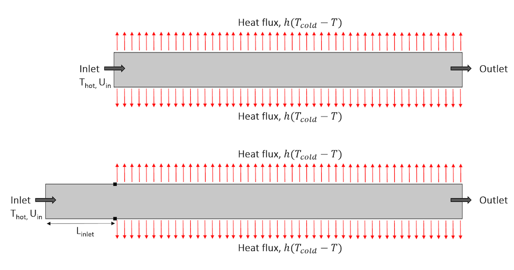
Representation of the geometry with a section before the area exposed to the heat flux (top) and with the inlet at the beginning of the area exposed to the heat flux (bottom).
Now we solve the model using either a Temperature or Inflow boundary condition at the inlet. We vary two parameters in the model:
- Inlet velocity, Uin: 1 cm/s and 10 cm/s
- Length of the channel before the area exposed to the heat flux, Linlet: 0, 0.2, 1, and 2 cm
The goal of these simulations is to determine the values of Linletfor which we are able to set accurate thermal boundary conditions using Temperature and Inflow boundary conditions, respectively.
Simulation Results for the Highest Inlet Velocity
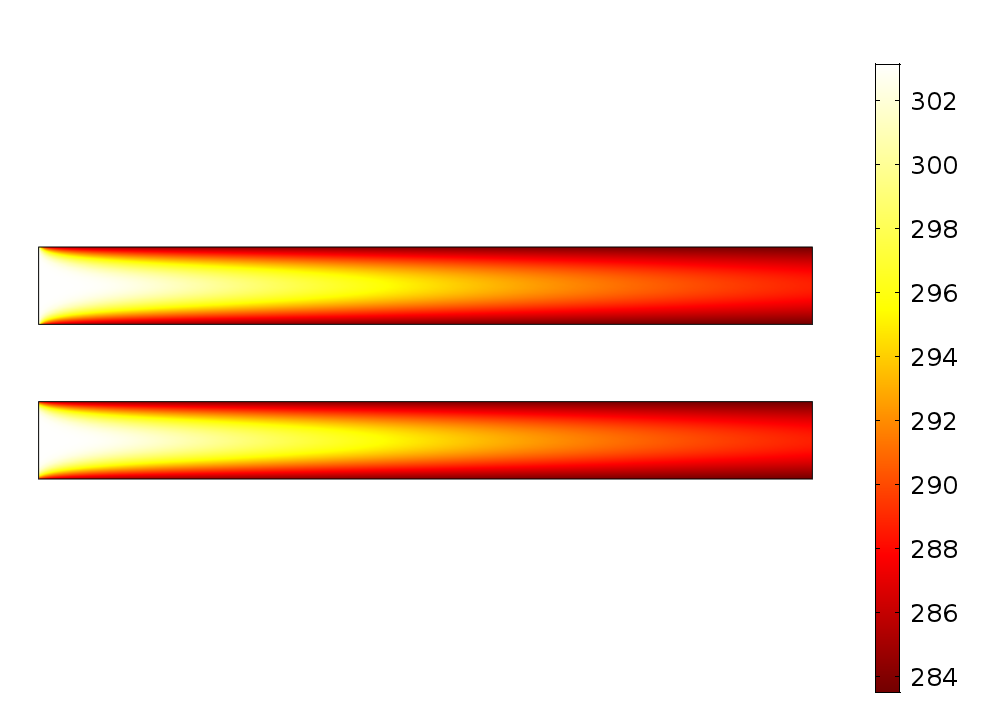
Let’s comment on the results for Uin = 10 cm/s. In the left part of the figure below, we see the temperature profile using the Temperature boundary condition (top) and the Inflow boundary condition (bottom). The two graphs look very similar and it is difficult to draw any conclusion from them, but the graph on the right gives more details.
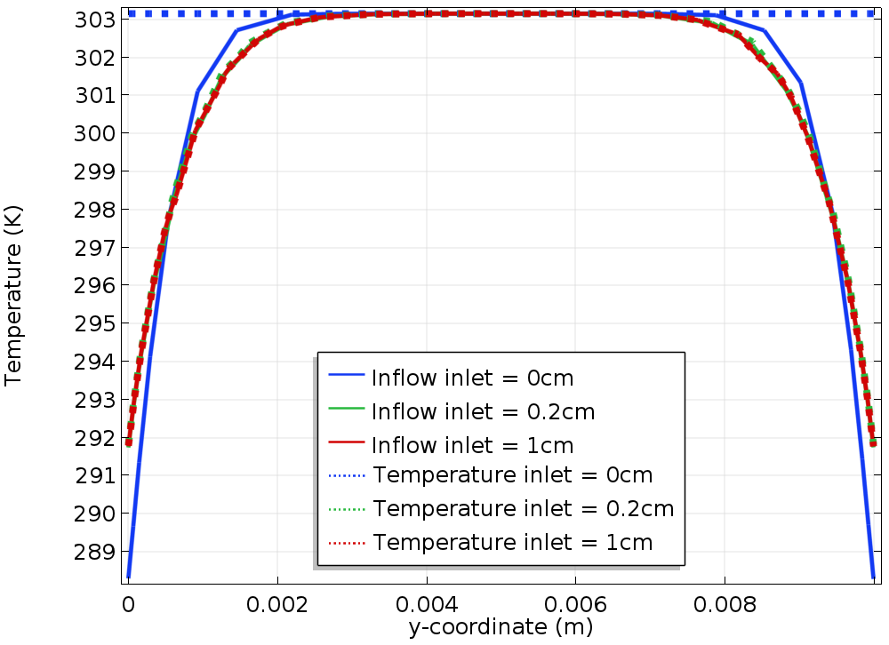
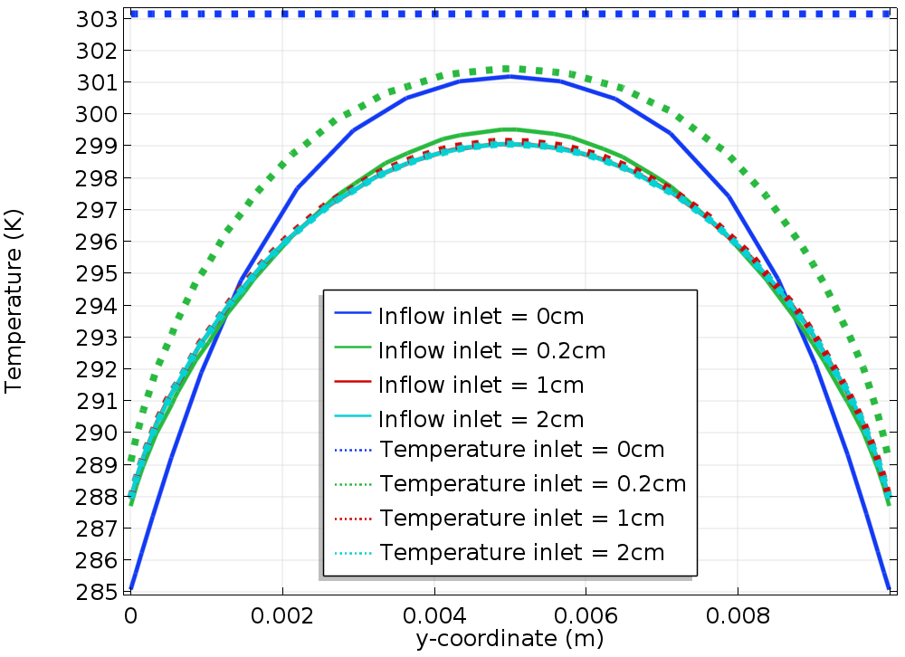
The graph to the right shows the temperature profile along the vertical line located at the beginning of the cooling zone. (It coincides with the inlet boundary, when Linlet = 0. Let’s call it “reference line” in the rest of this blog post.) The solid lines represent the results obtained using an Inflow boundary condition and the dotted lines correspond to the Temperature boundary condition. The different colors correspond to different values of Linlet.
Let’s first check the results obtained using the Temperature boundary condition (dotted line). We see that as Linlet increases, the temperature profile along the reference line converges to a given profile. The results for Linlet = 2 cm show no improvement; they coincide with the results obtained for Linlet = 1 cm, so we can consider that there is no need to further extend the channel.
For Linlet = 0, the temperature profile is quite different from the converged profile. This illustrates a classical issue using a Temperature boundary condition: As the temperature profile is not known in advance along the reference line, the best option is to prescribe a reasonable temperature; here, the upstream temperature.
When an Inflow boundary condition is used, if the value of Linlet is increased, the temperature profile along the reference line convergences to the same profile as when a Temperature boundary condition is used.
We notice that especially with Linlet = 0, the solution is much closer to the converged profile than when using the Temperature boundary condition.
Left: Temperature field in the channel using the Temperature boundary condition (top) and Inflow boundary condition (bottom) for Linlet = 0 and Uin = 10 cm/s. Right: A comparison of the temperature along the reference line with the Inflow boundary condition (solid line) and the Temperature boundary condition (dotted line).
It is important to keep in mind that in many projects, the geometry contains inlets that are fed by channels that are not represented in the geometry. While for simple geometries — like here — it is easy to modify it to include a part of the channel before the inlet, it can be challenging for advanced geometries. Even with Linlet = 0, the Inflow boundary condition gives a decent prediction of the temperature profile at the inlet.
When the channel before the inlet can be extended a sufficient distance, the temperature profile on the inlet boundary obtained using Inflow and Temperature boundary conditions coincide. This is in agreement with the analysis made before stating that when the advective heat transfer dominates and an ideal gas model is used, the Inflow boundary condition is similar to a Temperature boundary condition. It is interesting to mention here that from a numerical point of view, the two conditions behave similarly in this case. (For example, the number of iterations taken by the nonlinear solver is identical for both conditions.)
Apart from the temperature profile, another quantity that should be monitored is the heat rate induced by the heat flux. The table below contains this heat rate for the different values of Linlet. One column contains the value for the Inflow boundary condition and the other for the Temperature boundary condition.

The heat rate tabulated for the case with highest inlet velocity.
When the Inflow boundary condition is used, the heat rate is almost constant. When using a Temperature boundary condition, the heat rate is affected by the value of Linlet.
Simulation Results for the Lowest Inlet Velocity
Because the velocity is lower in this case, the advective effects no longer dominate. The image below to the left shows the temperature field obtained using the Temperature boundary condition (top) and Inflow boundary condition (bottom). Although the two plots look similar, a closer look at them reveals that at the end of the inlet boundary, there is a difference between the two temperature profiles.
The graph to the right shows the temperature profile along the reference line. As before, the solid lines represent the results obtained using an Inflow boundary condition, the dotted lines correspond to the Temperature boundary condition, and the different colors correspond to different values of Linlet.
Again, for Linlet = 0, the Temperature boundary condition prescribes a constant temperature along the reference line. This temperature profile is far from the solution obtained with the largest values of Linlet. As before, we see that as Linlet increases, the temperature converges to a given profile. However, here, the convergence is slower, compared to the case with Uin = 10 cm/s. Comparing the solution obtained using the Inflow boundary condition and the Temperature boundary condition, we notice that for any value of Linlet, the solution obtained using the Inflow boundary condition is always closer to the converged profile.
Left: Temperature field in the channel using the Temperature boundary condition (top) and Inflow boundary condition (bottom) for Linlet = 0 and Uin = 1 cm/s. Right: Comparison of the temperature along the reference line for the Inflow boundary condition (solid line) and the Temperature boundary condition (dotted line).
The table below again shows the heat rate for the two boundary conditions.

The heat rate tabulated for the case with the lowest inlet velocity.
The trend is similar to the first case, but when a Temperature boundary condition is used, the influence of Linlet on the heat rate is much larger. Using a Temperature boundary condition with Linlet = 0, the value of the heat rate is overestimated by a factor of almost 2 compared to the solution obtained with a long inlet. Using an Inflow boundary condition, the heat rate is correctly predicted for any value of Linlet.
These results show that when Linlet is small (especially when Linlet = 0), the temperature profile and the heat flux are more realistic using an Inflow boundary condition rather than a uniform Temperature boundary condition. This can be explained by the fact that at the inlet, a uniform temperature profile is not realistic. In practical situations, the temperature is not controlled exactly at the inlet but, for example, in a tank located at some distance.
Concluding Thoughts
While in many configurations, the Temperature and Inflow features describe similar conditions and lead to similar simulation results, there are a number of configurations (especially for slow flow and small dimensions) where the conductive effects are not dominated by the advective effects and where the Inflow boundary condition usually leads to a temperature profile that is closer to the reality than a Temperature boundary condition. In addition, a Temperature boundary condition could enforce an erroneous temperature value that induces large heat fluxes that are not realistic.
As the Inflow boundary condition is simple to use and usually does not induce an additional numerical cost to be solved, it ought to be the first choice to define a heat transfer condition at the flow inlet. The vast majority of model examples in the Application Libraries use it.
Next Step
Learn more about all of the functionality available for heat transfer modeling in COMSOL Multiphysics by clicking the button below.
Notations
C_p: Heat capacity (SI unit: J/K/kg)
h: Heat transfer coefficient (SI unit: W/m2/K)
\mathbf{n}: Boundary normal vector (SI unit: 1)
k: Thermal conductivity (W/K/m)
p: Pressure (SI unit: Pa)
\mathbf{q}: Heat flux (SI unit: W/m2)
p_{\mathrm{upstream}}: Pressure of the upstream (SI unit: Pa)
T: Temperature (SI unit: K)
T_{\mathrm{cold}}, T_{\mathrm{hot}}: Cold and hot temperatures (SI unit: K)
T_{\mathrm{upstream}}: Temperature of the upstream (SI unit: K)
U_{\mathrm{in}}: Inlet velocity (SI unit: m/s)
\alpha_p: Coefficient of thermal expansion (SI unit: 1/K)
\rho: Density (SI unit: kg/m3)
\mathbf{u}: Velocity (SI unit: m/s)
\Delta H: Enthalpy change vs. reference enthalpy (SI unit: J/kg)





Comments (0)