
With the release of COMSOL Multiphysics® version 5.2a, it is now possible to trace rays in unmeshed domains and even release and trace rays outside a geometry. The Ray Optics Module provides an entirely new algorithm that offers these capabilities and more, so that you can model your ray optics designs with ease and accuracy. Let’s investigate how this new algorithm affects your workflow when setting up a typical ray optics model.
Tracing Rays Outside Meshed Domains
In previous versions of the Ray Optics Module, rays can only be released and propagate in meshed domains. This is because the mesh elements are used in many fundamental parts of the ray tracing process, such as detecting boundary interactions, querying the refractive index of the domain, and with some advanced features such as accumulators.
In version 5.2a, if a ray is not in any mesh element, it is still able to detect boundary interactions as long as the boundaries themselves are meshed. In practice, this means that you can model reflection at a surface as long as the surface is meshed, even if it isn’t adjacent to a domain mesh. You can even create “floating” surfaces that are not adjacent to any domain. In addition, it is possible to specify a refractive index for the unmeshed regions.
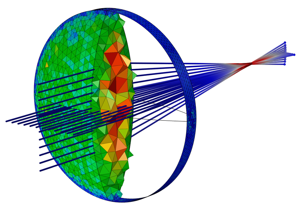
A collimated beam is focused by a convex lens. The rays can propagate in the lens and in the region outside the geometry where no mesh is defined. The color expression on the rays is based on their intensity, while the color of the mesh is proportional to the element size.
This new algorithm means that rays can be accurately traced outside of meshed domains as long as the following conditions are met:
- The medium is homogeneous, isotropic, and doesn’t depend on field variables (such as temperature).
- All unmeshed regions have the same refractive index.
- Advanced mesh-dependent features like domain accumulators aren’t needed in the unmeshed regions.
- All boundaries that affect ray propagation are meshed. This includes boundary conditions such as material discontinuities, absorbing or scattering walls, diffraction gratings, and optical components such as linear polarizers.
Modeling a Simple Lens System Example
Let’s start with a simple example. We construct a 2D model in which rays are focused by a pair of cylindrical convex lenses.
In the previous version of COMSOL Multiphysics, version 5.2, it is necessary to create a geometry consisting of the two lenses and a surrounding air or vacuum domain, as shown below. Rays start to the left of the first lens and propagate in the positive x direction. The color expression is proportional to the logarithm of the ray intensity.
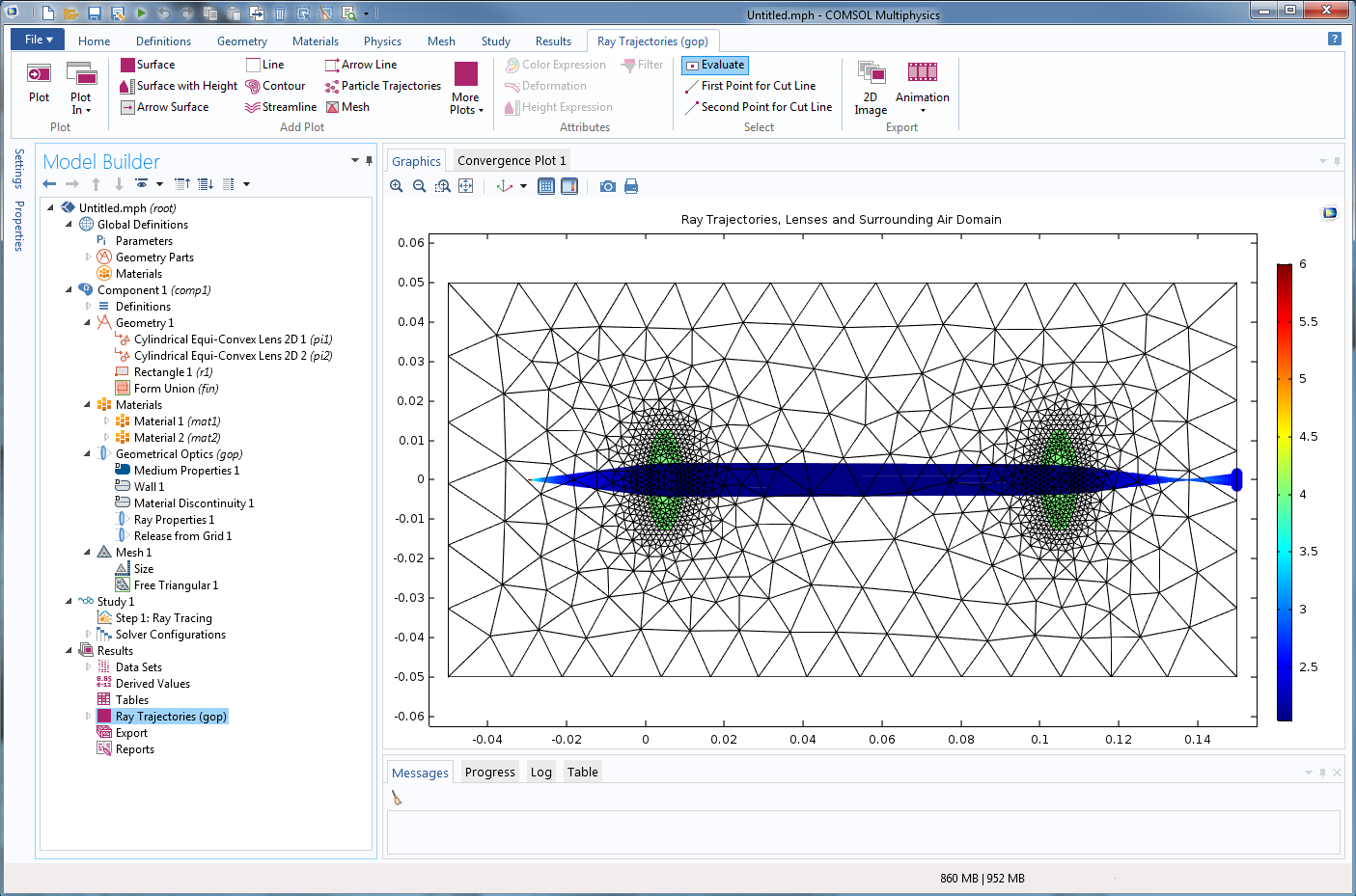
Simulating a simple ray optics lens system in COMSOL Multiphysics version 5.2.
Let’s take a closer look at the Model Builder and the geometry. The geometry sequence includes two instances of the Cylindrical Equi-Convex Lens part from the built-in Part Library for the Ray Optics Module. These lenses are shown in green. It also includes a rectangle containing air (n = 1). Both lenses and the surrounding air domain must be meshed. If rays are released outside the air domain, or if the mesh in the air domain is omitted, the rays disappear immediately and can never propagate.
Now, let’s consider the same model, built in version 5.2a.
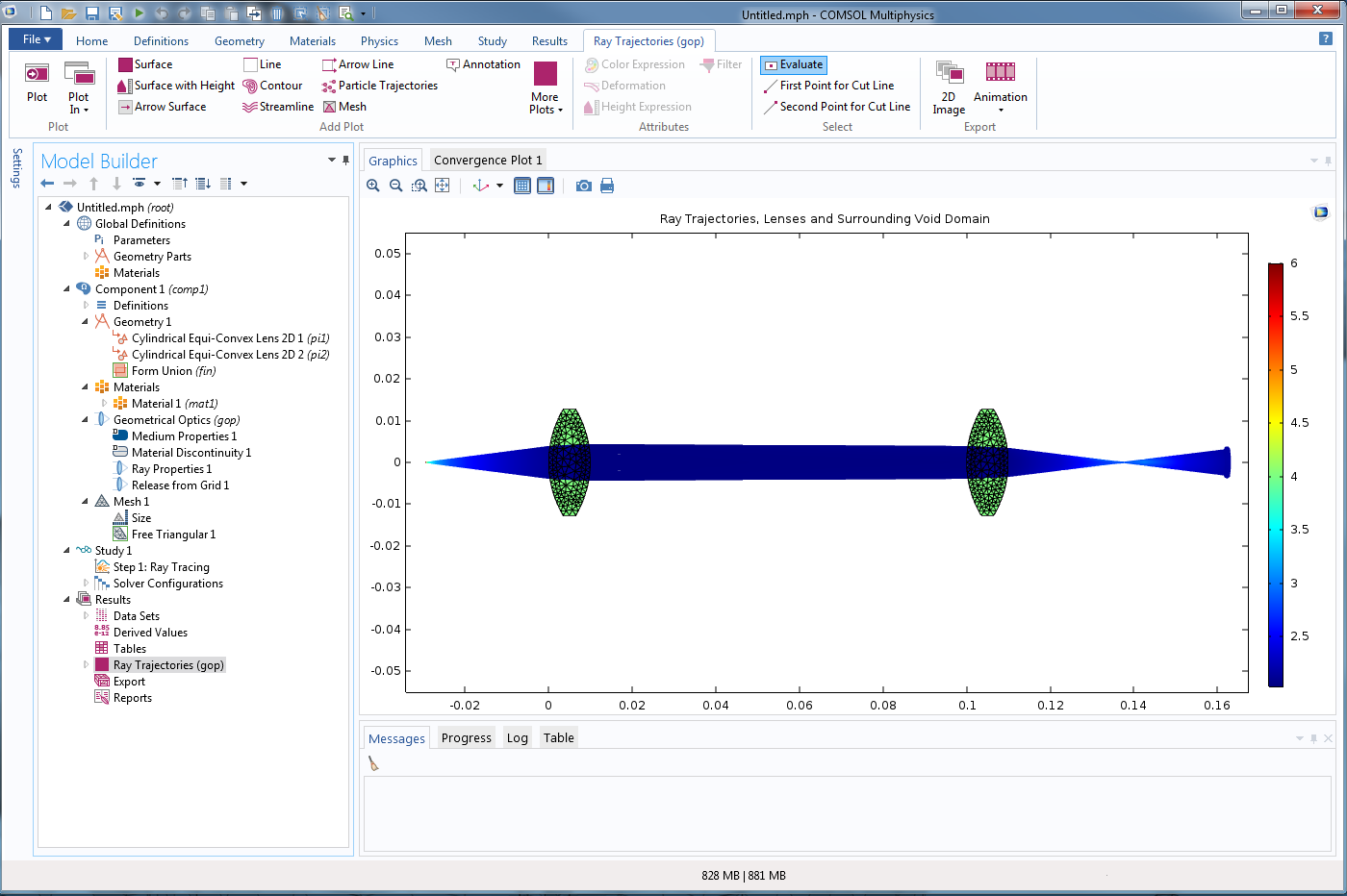
The same lens example in the latest version of COMSOL Multiphysics, version 5.2a.
The most obvious change is that the air domain is gone. Rays can still be traced in this void region outside the geometry and you can still specify its refractive index. Another advantage of omitting the air domain is that you can change the focal length of the lenses without worrying about whether you need to resize the surrounding domain to capture all of the relevant physics. Rays can continue to propagate for as long as you want them to.
Note the difference in the default boundary conditions in the Model Builder. In version 5.2, a Wall boundary condition is automatically applied to exterior boundaries, and the Material Discontinuity boundary condition is applied to interior boundaries. In version 5.2a, Material Discontinuity is applied to interior and exterior boundaries by default, emphasizing the fact that the rays are no longer bound by the selection of the Geometrical Optics physics interface.
While it is now possible to trace rays outside the geometry, some advanced features won’t work in void domains or unmeshed domains. For instance, in the above example, it would not be possible to define a Deposited Ray Power feature to the air outside the geometry, because this feature deposits the absorbed ray power on mesh elements.
Essentially, you can think of the unmeshed regions of space as the selection of a “Geometrical Optics lite” interface, where basic functionality like ray propagation, reflection, refraction, and absorption are supported, but more specialized phenomena like heating and propagation in graded media are not supported. Since it is possible to trace rays through any combination of meshed and unmeshed domains, the solution is usually to mesh the domains in which these more specialized phenomena must be considered.
Physics-Controlled Meshing
As I mentioned earlier, although ray propagation through unmeshed domains is supported, rays can only interact with surfaces if a boundary mesh is present. A mesh sequence with the default Physics-controlled mesh automatically sets up the following mesh sequence:
- All domains in the selection of the Geometrical Optics interface are meshed. Any boundaries adjacent to these domains are therefore also meshed.
- All surfaces that have a boundary condition applied to them are meshed. This is true even if the surfaces are not adjacent to any domain in the above bullet point.
The following screenshot demonstrates this physics-controlled mesh sequence. The geometry is an array of 9 cubes in a 3-by-3 array. Three of these cubes are included in the selection of the Geometrical Optics interface. The geometry and mesh are shown below.
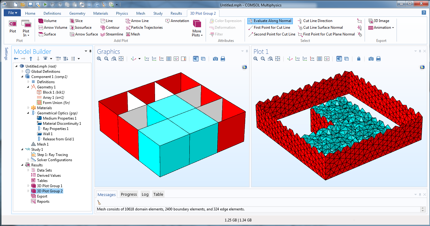
The geometry and mesh for a physics-controlled mesh sequence for an array of cubes.
In the left plot, the selection of the Geometrical Optics interface is shown in cyan. The exterior and interior boundaries of this selection are automatically assigned the Material Discontinuity boundary condition. Additional boundaries (shown in red) are then assigned the Wall boundary condition. Some interior boundaries (shown in white) and some boundaries on the top and bottom surfaces (not shown) are not assigned any boundary condition at all.
A Physics-controlled mesh is then generated with the Finer size. The resulting mesh is shown in the right plot. The domain mesh is shown in cyan and the boundary mesh is shown in red. An element filter has been used to display a cross section of the volume elements. Note that all domains outside the selection of the Geometrical Optics interface are left unmeshed, as well as any boundaries that have no boundary condition applied to them.
Updated Application Library Examples with the New Ray Tracing Algorithm
Most of the ray tracing examples in the Application Library have been changed in version 5.2a. Usually, this involves a simplification of the geometry and the model setup, since it is no longer necessary to draw air boxes around all geometric entities.
Czerny-Turner Monochromator
In the Czerny-Turner Monochromator tutorial model, polychromatic light is separated into different colors using a collimating mirror, focusing mirror, and diffraction grating, which are arranged in a crossed Czerny-Turner configuration. For more detailed information about the model, see this previous blog post.
In version 5.2, the model uses an air domain that surrounds the mirrors and grating. The mesh and the resulting ray trajectories are shown below.
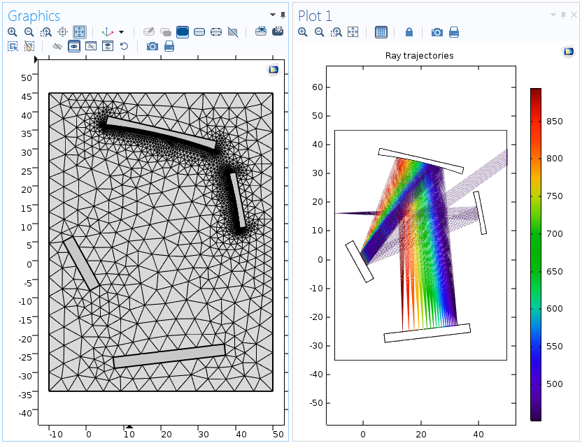
The mesh (left) and ray trajectories (right) in a Czerny-Turner monochromator in COMSOL Multiphysics version 5.2.
In version 5.2a, the air domain is completely omitted. In fact, the selection list for the Geometrical Optics interface is completely empty and the model includes no domain-based physics features or domain mesh, only boundary conditions and boundary mesh elements. Note that the mesh on the left is automatically applied to all surfaces where the rays are reflected, either by a Wall feature or a Diffraction Grating. The only manual change to the mesh sequence is a refinement on the curved collimating mirror and focusing mirror by specifying a small Curvature factor in the mesh settings.
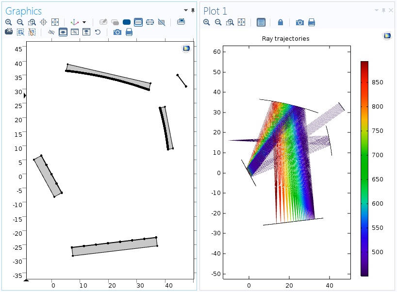
The mesh (left) and ray trajectories (right) for the same model, shown with the updated functionality in version 5.2a.
Thermally Induced Focal Shift
Thermally induced focal shift is a phenomenon that is frequently seen in high-powered laser focusing systems, where the heat generated by the laser degrades the focusing capability of the system due to phenomena such as thermal expansion of the lenses and temperature- and strain-dependent refractive indices.
In version 5.2, it is necessary to create an air domain surrounding the lenses. One of the factors that can make thermally induced focal shift difficult to model is that, for any deformation in the lenses, a corresponding deformation in the surrounding air domain is also needed. This means that in version 5.2, a Moving Mesh interface has to be applied to the air domain.
In the following image, the lens domains (red) are used as the selection for the Heat Transfer in Solids and Solid Mechanics interfaces. The air domain (white) is the selection for the Moving Mesh interface. All three domains are included in the selection for the Geometrical Optics interface.
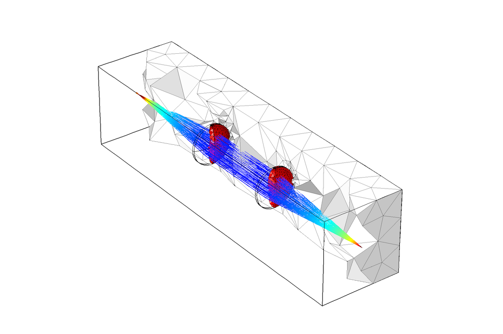
Modeling thermally induced focal shift in in COMSOL Multiphysics version 5.2.
In COMSOL Multiphysics version 5.2a, the Moving Mesh interface is no longer needed. The only domains in the geometry are the two lenses and rays are free to propagate in the surrounding empty space. This greatly reduces the clutter in the model, as shown below. Because it is no longer necessary to use the Moving Mesh interface, the model is now considerably easier to set up and requires fewer degrees of freedom for the same mesh element size.
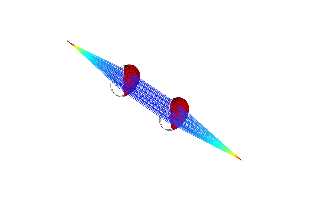
Simulating the same thermally induced focal shift in version 5.2a.
Luneburg Lens
A Luneburg lens contains a spherically symmetric graded-index medium that can be used to focus collimated rays. As I mentioned earlier, however, to trace rays in unmeshed domains, it is necessary for the medium to be homogeneous; i.e., graded-index media are not allowed. The solution is to include the graded-index domain in the selection of the Geometrical Optics interface, so that a domain mesh will automatically be created by the physics-controlled mesh sequence. The region outside the lens, in which the refractive index is uniform, can be excluded from the geometry. In this case, the region outside the geometry is assumed to have a unit refractive index.
The lens domain is a sphere of radius R in which the refractive index n is a function of the radial coordinate r:
where f is a dimensionless parameter that controls the location of the focus of the paraxial rays.
For f=1, the focus lies on the surface of the sphere, while for f>1, the focus lies outside the sphere. Note that for any positive value of f, the refractive index on the exterior of the sphere (r=R) is always unity; thus, there is no reflection or refraction anywhere in the model and all changes in ray direction are solely due to the gradient of the refractive index.
The ray paths in the lens are shown below for f=1.1. Parallel rays enter from the left and are focused by the lens. The color expression in the spherical domain is proportional to the refractive index, which reaches a maximum value at the center. The color expression along the ray trajectories is proportional to the logarithm of ray intensity.
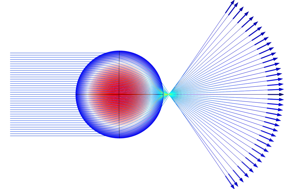
Ray paths in a Luneburg lens.
Restricting Propagation Outside Selected Domains
The new capability to release rays outside the geometry will be available by default, either in new models or when opening an old model in version 5.2a. It is possible to disable this new functionality, however, so that rays will again disappear if they are released or propagate outside of the meshed domains. To restrict rays to propagation in meshed domains only, first enable Advanced Physics Options, as shown below. Then clear the Allow propagation outside selected domains check box in the Advanced Settings window of the physics interface.
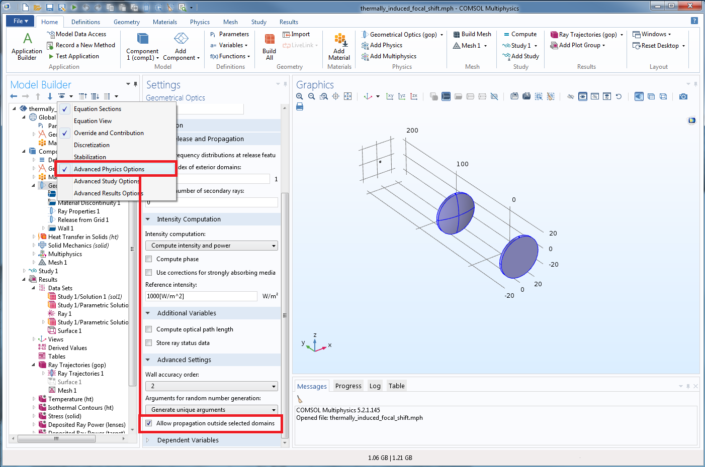
You can easily disable the new default functionality for releasing rays outside your model geometry.
Further Resources on Ray Optics and COMSOL Multiphysics® Version 5.2a
- Read more about all of the updates in COMSOL Multiphysics version 5.2a on the Release Highlights page
- Browse the COMSOL Blog to see other applications and detailed demonstrations of ray optics simulations
- Find a free training event online or near you to learn about the ins and outs of ray optics modeling and the latest COMSOL Multiphysics functionality




Comments (1)
Ivar Kjelberg
June 23, 2016Hello Christopher,
that looks great 🙂
I’ll check those new features, and plots, asap
Sincerely
Ivar