
When you first try to run a particle tracing simulation with very small particles in a fluid — generally tens of microns in diameter or smaller — you might notice the time-dependent solver taking much shorter time steps than usual. This is often due to the particle equations of motion exhibiting numerical stiffness. In this blog post, we’ll introduce the concept of stiffness as it pertains to particle simulation, then offer some guidelines for choosing the correct equation formulation based on particle size.
Example: Gravitational Settling of a Small Sphere
Let’s consider a small, spherical particle as it falls through a surrounding fluid of uniform velocity u (SI unit: m/s). The particle follows Newton’s second law of motion,
(1)
where
- mp (SI unit: kg) is the particle mass
- q (SI unit: m) is the particle position vector
- Ft (SI unit: N) is the net force or total force acting on the particle
For a particle sinking in a fluid, the total force is the sum of the gravity force Fg and the drag force FD,
(2)
\qquad
\mathbf{F}_\textrm{D} = 3\pi \mu d_\textrm{p}\left(\mathbf{u}-\mathbf{v}\right)
where
- ρp (SI unit: kg/m3) is the density of the particle
- ρ (SI unit: kg/m3) is the density of the surrounding fluid
- g (SI unit: m/s2) is the acceleration due to gravity (about 9.8 m/s2 downward at sea level)
- μ (SI unit: Pa s) is the dynamic viscosity of the surrounding fluid
- dp (SI unit: m) is the particle diameter
- u (SI unit: m/s) is the velocity of the surrounding fluid
- v (SI unit: m/s) is the velocity of the particle (v ≡ dq/dt)
The term (ρp – ρ)/ρp in the expression for the gravitational force represents buoyancy. It approaches 1 when the particles are much heavier than the fluid they displace — solid particles in air, for example. It approaches zero when the particle and the surrounding fluid have equal density, in which case the particles are called neutrally buoyant.
The expression for the drag force used here is from the Stokes drag law. It is appropriate to use this drag law when the relative Reynolds number of the particle is very small,
\textrm{Re}_\textrm{r} \equiv \frac{\rho d_\textrm{p}\left|\mathbf{u}-\mathbf{v}\right|}{\mu} \ll 1This is more likely to be valid for smaller particles.
Assume the particles are not changing size (thus dp and mp are constant). The mass of a sphere is
(3)
By combining Eqs. 1–3, we arrive at a simplified expression for the particle’s equation of motion,
(4)
=
\frac{\rho_\textrm{p}-\rho}{\rho_\textrm{p}}\mathbf{g}
+
\frac{1}{\tau_\textrm{p}}\left(\mathbf{u}-\mathbf{v}\right)
where the constant τp has been introduced,
τp has units of time and is usually called the Lagrangian time scale or the particle velocity response time, for reasons that will soon be apparent.
As a further simplification, assume the surrounding fluid is quiescent (u = 0) and that the particle is initially at rest (q = 0 and v = 0 at time t = 0). Suppose we align our coordinate system so that the gravity vector points in the –y direction. Then, continuing from Eq. 4, the equation for the y-component of the particle position becomes
(5)
=
-\frac{\rho_\textrm{p}-\rho}{\rho_\textrm{p}}g-\frac{1}{\tau_\textrm{p}}v_y
The exact or analytic solution to Eq. 5, given the initial conditions qy = 0 and vy = 0, is
q_y &= -v_\textrm{t}\left\{t+\tau_\textrm{p}\left[\exp\left(-\frac{t}{\tau_\textrm{p}}\right)-1\right]\right\}\\
v_y &= -v_\textrm{t}\left[1-\exp\left(-\frac{t}{\tau_\textrm{p}}\right)\right]\\
\end{aligned}
where vt is the terminal velocity,
Conversion to Dimensionless Variables
To get a better understanding of how the particle accelerates during the first few multiples of τp, we can replace the time, position, and velocity (t, qy, vy) with the corresponding dimensionless quantities (t‘, qy‘, vy‘), defined as
q_y^{\prime} \equiv \frac{q_y}{v_\textrm{t}\tau_\textrm{p}} \quad\quad \\
v_y^{\prime} \equiv \frac{v_y}{v_\textrm{t}}
Substituting these dimensionless variables back into the analytic solution yields
q_y^{\prime} &= -t^{\prime}-\exp\left(-t^{\prime}\right)+1\\
v_y^{\prime} &= -1+\exp\left(-t^{\prime}\right)\\
\end{aligned}
In the figure below, the dimensionless position and velocity are plotted as functions of the dimensionless time t‘. This plot illustrates that the particle velocity asymptotically approaches the terminal velocity, with most of the acceleration happening during the first few multiples of the Lagrangian time scale τp. The particle position appears to change linearly after this initial acceleration period.
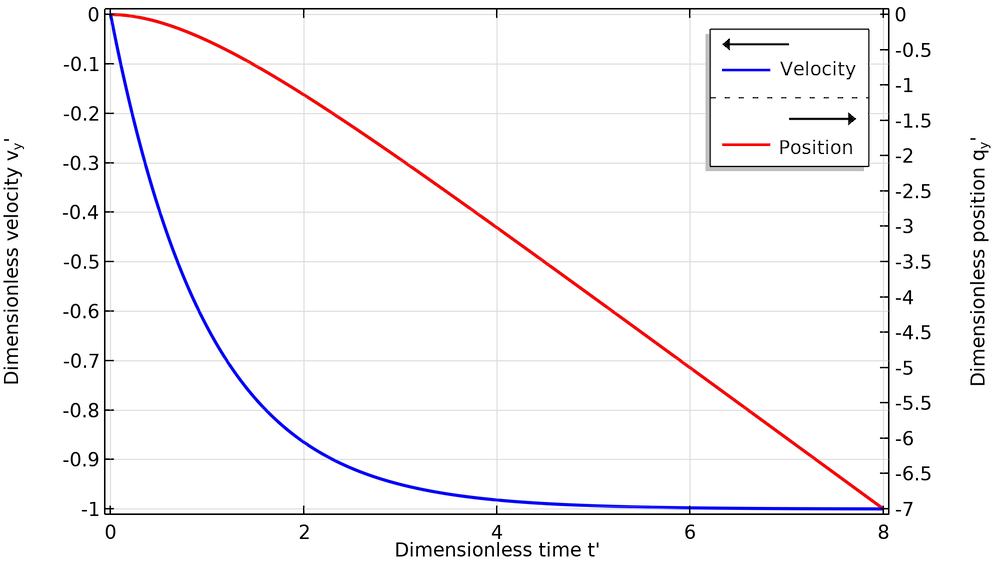
Plot of the dimensionless position and velocity of a particle undergoing gravitational settling, starting from rest.
Time Scales for Some Typical Particle Sizes
To get a better idea of the time scales involved in particle acceleration, suppose the particles are silica glass beads with a density of about 2200 kg/m3. The following table gives some values for the Lagrangian time scale in air and in water for different particle sizes.
| Fluid | Particle Diameter (μm) | Fluid Dynamic Viscosity (Pa s) | Fluid Density (kg/m3) | Response Time (s) | Terminal Velocity (m/s) |
|---|---|---|---|---|---|
| Water | 1 | 1.009 × 10⁻³ | 998.2 | 1.2 × 10⁻⁷ | 6.5 × 10⁻⁷ |
| Water | 20 | 1.009 × 10⁻³ | 998.2 | 4.8 × 10⁻⁵ | 2.6 × 10⁻⁴ |
| Water | 50 | 1.009 × 10⁻³ | 998.2 | 3.0 × 10⁻⁴ | 1.6 × 10⁻³ |
| Air | 1 | 1.814 × 10⁻⁵ | 1.204 | 6.7 × 10⁻⁶ | 6.6 × 10⁻⁵ |
| Air | 20 | 1.814 × 10⁻⁵ | 1.204 | 2.7 × 10⁻³ | 2.6 × 10⁻² |
| Air | 50 | 1.814 × 10⁻⁵ | 1.204 | 1.7 × 10⁻² | 0.17 |
The diameter-squared dependence of τp means that large particles have a much greater velocity response time and a much greater terminal velocity than small particles. This has two major consequences:
- Large particles fall to the ground much faster than small particles.
- When large particles are launched into a fluid with some initial velocity, they follow ballistic trajectories, capable of traveling a considerable distance before the drag force slows them down. In contrast, smaller particles will match the fluid velocity much sooner; when they spread out, it is more likely due to turbulent diffusion of the surrounding fluid.
Numerical Particle Tracking Simulation
In the previous section, we were quite lucky that Eq. 4 had an exact analytic solution. It was only possible to obtain an exact solution because of all of the simplifying assumptions involved, most notably that the fluid velocity u was zero everywhere. In most real-world systems, the velocity of the surrounding fluid is not only nonzero but also spatially nonuniform, and then it is very unlikely that an exact solution can be found with pen and paper alone.
For more general problems, we can turn to numerical simulation to get an approximate answer. The main idea is that, given the initial particle position q0 and velocity v0 at the initial time t = 0, we can use numerical time stepping algorithms to estimate the solution at a set of discrete time steps t1, t2, t3, etc. A wide variety of different time stepping algorithms have been devised for this purpose, many of which are available in the COMSOL Multiphysics® software.
Solving a set of differential equations numerically introduces some amount of error — the difference between the real-world particle motion and the computed numerical solution. While one usually cannot hope to get a perfect solution from a numerical simulation, a more realistic goal is that the simulated particle motion should become more accurate when the time intervals (t1, t2 – t1, t3 – t2, etc.) are reduced in size.
The trade-off is that if the time steps are smaller, you need to take more time steps to reach the same output time. Ultimately, this may lead to a noticeable increase in wall-clock time, which is how long the user must wait for the simulation to complete. Engineers working with numerical simulation must always seek a reasonable balance between solution accuracy and wall-clock time.
The Particle Tracing for Fluid Flow interface, available with the Particle Tracing Module, an add-on to COMSOL Multiphysics®, simulates the motion of individual particles in the surrounding fluid by solving Newton’s second law numerically. On a fundamental level, this interface solves Eq. 1 while allowing you to add a wide variety of different forces to the right-hand side. It also includes a variety of options for setting the initial particle position and velocity, as well as the detection and handling of particle collisions with surfaces in the surrounding geometry.
Dealing with Small Particles and Long Time Scales
In many practical applications, the range of desired solution times for a particle tracing model is much greater than the Lagrangian time scale τp. For example, suppose that we want to track the motion of some 20-μm silica glass particles in water over a total simulation time of 1 second. As we saw in the previous table, the Lagrangian response time for such small particles in water is about 5 × 10⁻⁵ seconds, so the total simulation time is about 2000 τp. If we wanted to track even smaller particles over a span of minutes or hours, it is easy to envision scenarios where our total simulation time could be millions of times larger than τp.
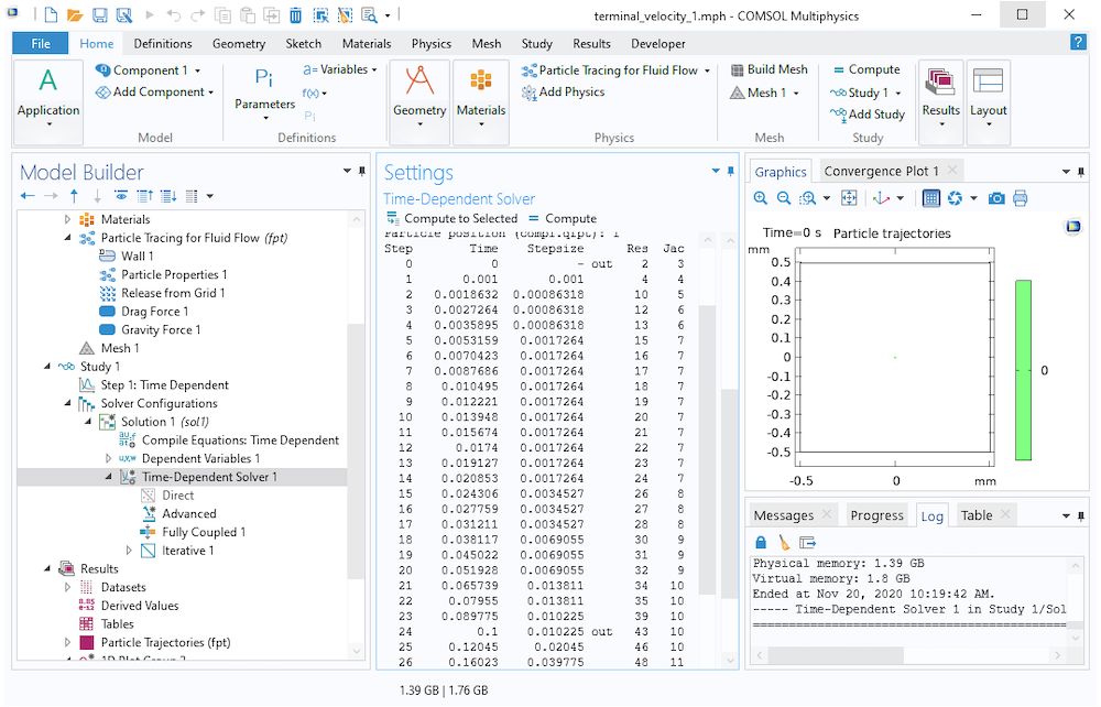
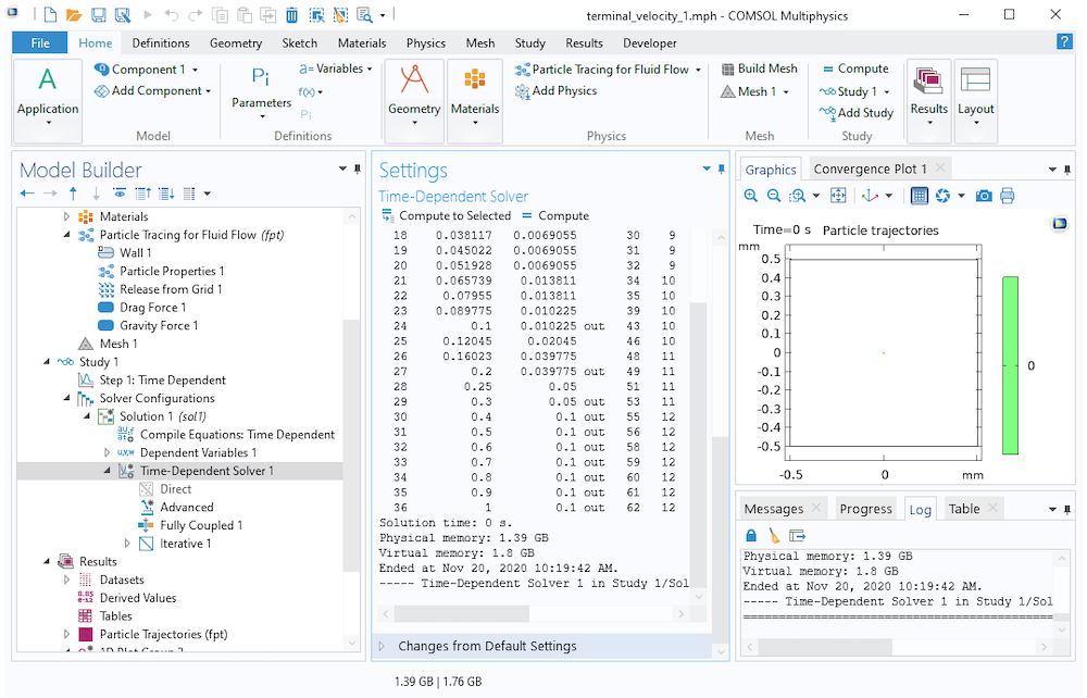
The following screenshot shows a log of the time steps taken by the time-dependent solver while tracking these 20-μm particles. The range of output times in the Step 1: Time Dependent node has been set to range(0,0.1,1), meaning that it will only store output at multiples of 0.1 s. However, this does not preclude the solver from taking smaller time steps if necessary to get an accurate solution. As shown here, the solver begins by taking time steps on the order of 1 ms or smaller, then gradually takes larger steps as the particle approaches its terminal velocity.
In COMSOL Multiphysics, the particle tracing physics interfaces generally use a Strict time stepping algorithm that requires at least some of the steps taken by the solver to coincide with the output times, such as step 24 below. This is not a general requirement of all physics; for some physics interfaces, the output times can be obtained by interpolation between the nearest steps taken by the solver.
Toward the end of the study, the time steps can be quite large because the particle is hardly accelerating at all. Ultimately, the solver takes 24 time steps to reach the first output time at 0.1 s, but only needs 12 more time steps to reach the final time at 1 s.
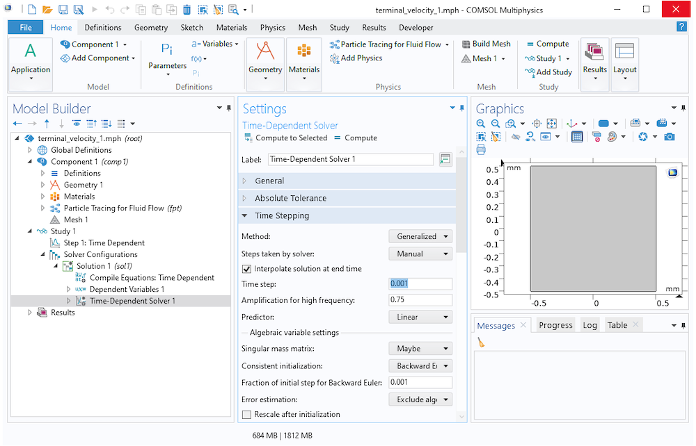
The equation of motion of a particle undergoing gravitational settling is an example of a stiff ordinary differential equation or stiff ODE. The default time stepping method used in most particle tracing models, called Generalized alpha, is a second-order implicit time stepping scheme that is rather good at handling stiff problems. If additional stability is required, there is a numerical damping term that can be adjusted in the Time-Dependent Solver settings, called the Amplification for high frequency. For this reason, the time steps are allowed to become larger as the particle velocity approaches the terminal velocity. (In contrast, the explicit Runge–Kutta method RK34 takes 7425 steps to solve the same problem!)
However, if particles were entering the simulation domain at several different release times, or if the background fluid velocity was spatially nonuniform (so that the particles could still accelerate later in the study), it might be necessary for the solver to continue taking such small time steps up until the final time. If we attempt to trace very small particles over a long simulation time, eventually these studies will require a substantial amount of wall-clock time to complete as the solver might take hundreds of thousands, or even millions of steps.
A closely related phenomenon that can be confusing to new COMSOL® software users involves releasing particles into the simulation domain using the Inlet boundary condition. Suppose these particles are assigned an initial velocity pointing into the simulation domain. Note from the previous screenshots that the initial time step size (for a total simulation time of 1 second) was 1 millisecond. If the initial time step size is still much greater than τp, the drag force might overcompensate, causing the particle velocity to briefly change direction and point back toward the Inlet boundary. If this happens, the particles might incorrectly detect a collision with the Inlet boundary, causing them to get stuck there.
Dealing with Numerical Stiffness in Particle Tracing Models
There are two main ways to deal with numerically stiff models of particle motion in a fluid — models in which the interval between the output times is several orders of magnitude greater than τp.
The first is what we call the “brute force” method: Simply tell the solver to take smaller time steps. If you don’t want to produce an overwhelming amount of output, potentially creating massive file sizes, you can instead leave the output times alone but specify a smaller step size or maximum step size in the settings for the time-dependent solver further down in the solver sequence.
The other approach, possible as of COMSOL Multiphysics® version 5.6, is to drop the inertial term from Eq. 4. First, we rewrite Eq. 4 as a pair of coupled first-order equations,
\frac{\textrm{d} \mathbf{q}}{\textrm{d}t} &= \mathbf{v}\\
\frac{\textrm{d} \mathbf{v}}{\textrm{d}t} &= \frac{\rho_\textrm{p}-\rho}{\rho_\textrm{p}}\mathbf{g} + \frac{1}{\tau_\textrm{p}}\left(\mathbf{u}-\mathbf{v}\right)\\
\end{aligned}
Now, instead of fully resolving the particle motion during the first few multiples of τp, we just assume that the drag force is always in dynamic equilibrium with all other applied forces,
(6)
+
\frac{1}{\tau_\textrm{p}}\left(\mathbf{u}-\mathbf{v}\right)
=
\mathbf{0}
In other words, we just assume the particle instantly reaches its terminal velocity. This is a fair approximation if the time required to approach the terminal velocity is many orders of magnitude smaller than the total simulation time. Eq. 6 can be solved for v,
or, more generally,
(7)
where Fother is the sum of all applied forces other than drag.
Then, all we have to do is integrate this expression for v over time to obtain the particle position q.
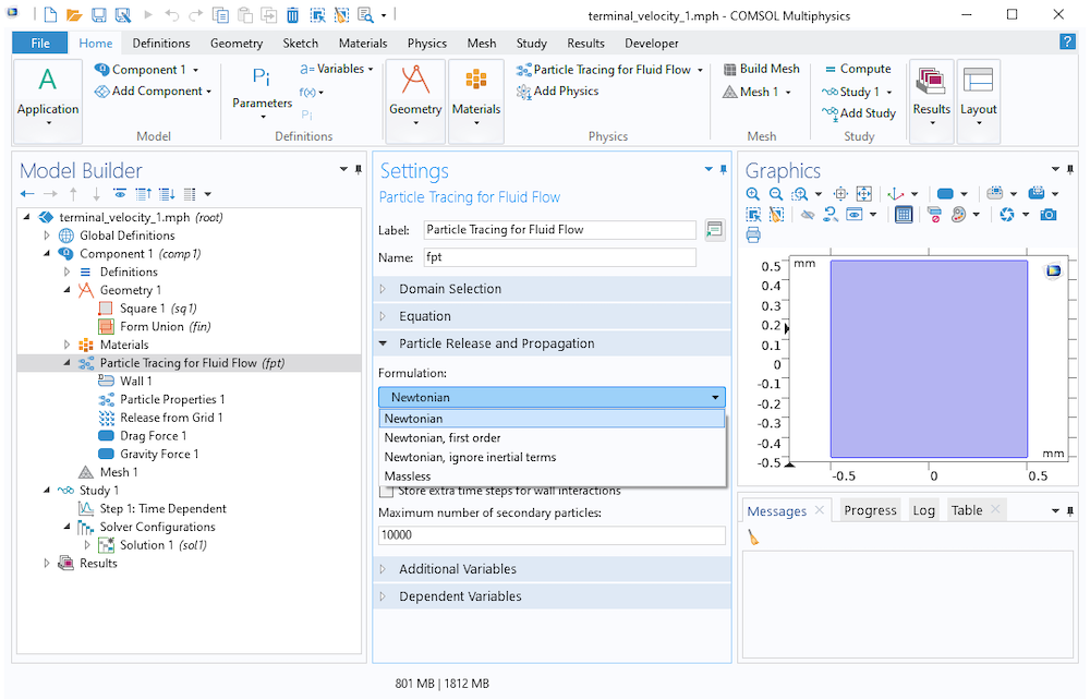
To choose which equation system the Particle Tracing for Fluid Flow interface will solve, locate the Particle Release and Propagation section. From the Formulation list, you can choose one of the following options:
- Newtonian: Solves Eq. 1
- Newtonian, first order: Separates Eq. 1 into a pair of coupled first-order equations for q and v, then solves them
- Newtonian, ignore inertial terms (available as of version 5.6): A simplified formulation that defines the velocity using Eq. 7, then solves for q
- Massless: An even more simplified formulation where you specify v directly in order to solve for q
Note that the number of available built-in forces is slightly greater for the Newtonian and Newtonian, first order formulations than for the Newtonian, ignore inertial terms formulation. Forces that explicitly depend on particle velocity or the relative positions of other particles have been excluded.
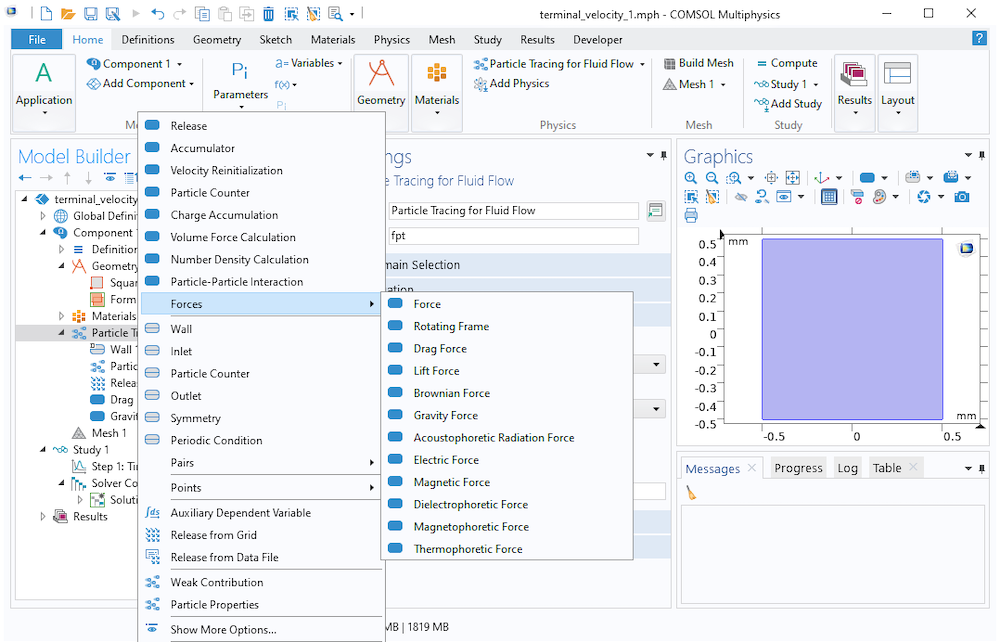
Available forces with the Newtonian formulation.
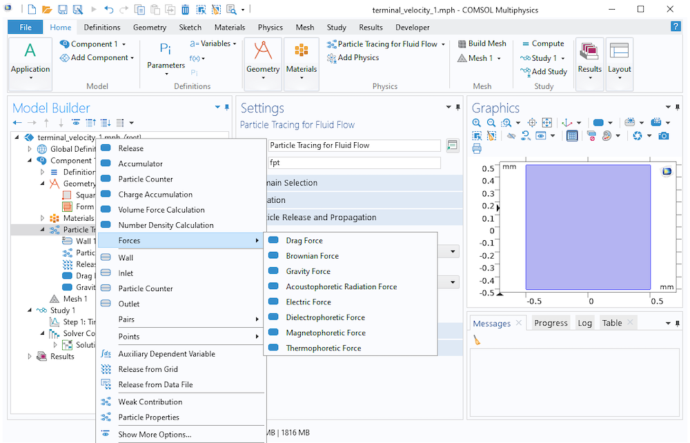
Available forces with the Newtonian, ignore inertial terms formulation.
The following Application Library examples use the Newtonian, ignore inertial terms formulation to trace very small particles for a long solution time:
- Particle Trajectories in a Laminar Static Mixer
- Dielectrophoretic Separation of Platelets from Red Blood Cells
The following examples use the Newtonian formulation because the particles are large enough for inertia to have a significant effect on particle motion:
Concluding Thoughts on Particle Tracing in Fluids
When simulating the motion of small particles in a fluid using the Particle Tracing for Fluid Flow interface, you should usually begin by estimating the Lagrangian time scale τp associated with the particles,
and comparing this time scale to the range of solution times you want to model.
If you have a distribution of different particle sizes, make this estimate based on the smallest particle size, since the smallest inertial particles in the model are the ones that determine how numerically stiff the equations of motion are.
If you want to predict the particle motion over a range of times much larger than the velocity response time (let’s just say, by a factor of several thousands or more), then you should consider whether inertia actually plays a significant role in the particle motion. If not, you can select the option Newtonian, ignore inertial terms (available as of version 5.6) from the Formulation list.
If you still want to consider inertia, you could use the Newtonian or Newtonian, first order formulation. However, note that the equation system being solved is numerically stiff, and you may need to manually reduce the size of the time steps taken by the solver to prevent nonphysical oscillations in the particle position and velocity.




Comments (5)
KF
March 23, 2021Thank you for the informative post! As a follow up question to the suggestion of implementing “Newtonian, ignore inertial terms” – does this assignment compromise wall-particle interactions, like bouncing?
Christopher Boucher
March 24, 2021 COMSOL EmployeeGood question. Switching to “Newtonian, ignore inertial terms” does prevent you from using certain options when particles collide with walls, such as bouncing. That’s because, with “Newtonian, ignore inertial terms”, we get the particle velocity directly from a force balance equation, rather than integrating the particle acceleration over time.
Leon Kamp
June 9, 2021I am very much interested in the case where the flow is laminar but not stationary. For a time-dependent flow streamlines and the trajectories of massless particles (say the fluid particles themselves) are not identical. How to proceed in such a case. Is it still possible to first calculate the flow is a first study and then integrate the particle paths? Or should the flow and the positions of the particles be simulated simultaneously since dq/dt=u=u(x,y,z,t)?
Vishal Anand
July 16, 2021Hi
Thank you for this informative post. I am trying to simulate the migration of a rigid sphere (finite sized, undergoing both rotation and translation) in different types of fluids:
1. Shear thinning fluids (Carreau model)
2. Viscoelastic fluids (Giesekus model)
Can these analyses be carried out in COMSOL? What modules should I use? Please advise
Santhosh Kumar Dontha
April 17, 2023How can we get the non spherical particle