
In the RF Module, an add-on to the COMSOL Multiphysics® software, high-frequency electromagnetics phenomena are addressed through several physics interfaces combined with different types of study steps. In this blog post, we review not only these physics interfaces and study steps but also a selection of RF Module Application Library examples applicable to each.
4 Physics Interfaces for RF Analyses
In the RF Module, there are four physics interfaces available to analyze electromagnetic wave propagation and resonance behavior both in the time and frequency domains. The following table summarizes the governing equation being solved for and the numerical method for each physics interface:
| Physics Interface | Governing Equation | Numerical Method |
|---|---|---|
| Electromagnetic Waves, Frequency Domain | \nabla \times {\mu_{\textrm{r}}^{-1}( \nabla \times {\mathbf{E}})} – k_0^{2}(\epsilon_{\textrm{r}} – \frac{j\sigma}{\omega\epsilon_0})\mathbf{E} = \mathbf{0} | Frequency domain finite element method (FDFEM) |
| Electromagnetic Waves, Transient | \nabla \times {\mu_{\textrm{r}}^{-1}( \nabla \times {\mathbf{A}})} + \mu_0 \sigma\frac{\partial\mathbf{A}}{\partial t} + \mu_0 \frac{\partial}{\partial t} \left(\epsilon_0\epsilon_{\textrm{r}}\frac{\partial\mathbf{A}}{\partial t}\right) = \mathbf{0} | Time domain finite element method (TDFEM) |
| Electromagnetic Waves, Time Explicit | \epsilon_0\epsilon_\textrm{r} \frac{\partial\mathbf{E}}{\partial t}-{\nabla}\times{\mathbf{H}}+{\sigma}\mathbf{E}=0 \mu_0\mu_\textrm{r} \frac{\partial\mathbf{H}}{\partial t}+{\nabla}\times{\mathbf{E}}=0 |
Time domain discontinuous Galerkin (DG) |
| Transmission Line | \frac{\partial}{\partial x}\left(\frac{1}{R+i\omega L}\frac{\partial V}{\partial x}\right) – (G+i\omega C)V=0 | Frequency domain finite element method (FDFEM) |
A time-harmonic (frequency-domain) simulation of a conventional h-bend waveguide model. The full harmonic dynamic data extension in the animation creates the look and feel of a time-domain propagation from a frequency-domain simulation.
Let’s go over each of these interfaces, as well as their associated studies and uses, in more detail…
Electromagnetic Waves, Frequency Domain
The most common approach to modeling RF, microwave, and millimeter-wave devices is the Electromagnetic Waves, Frequency Domain physics interface, which solves the wave equation based on the electric field variable. This physics interface is connected to various study types used to compute resonant frequencies, propagation constants, near and far fields, S-parameters, and more.
The various study steps and combinations that can be linked to this physics interface include:
- Mode Analysis
- Frequency Domain
- Boundary Mode Analysis and Frequency Domain
- Eigenfrequency
- Eigenfrequency and Frequency Domain, Modal
- Adaptive Frequency Sweep
- Frequency Domain and Frequency to Time FFT
Mode Analysis
The Mode Analysis study step performs eigenvalue analyses on the 2D transverse cut cross section of a waveguide or a transmission line to compute the resonant modes.
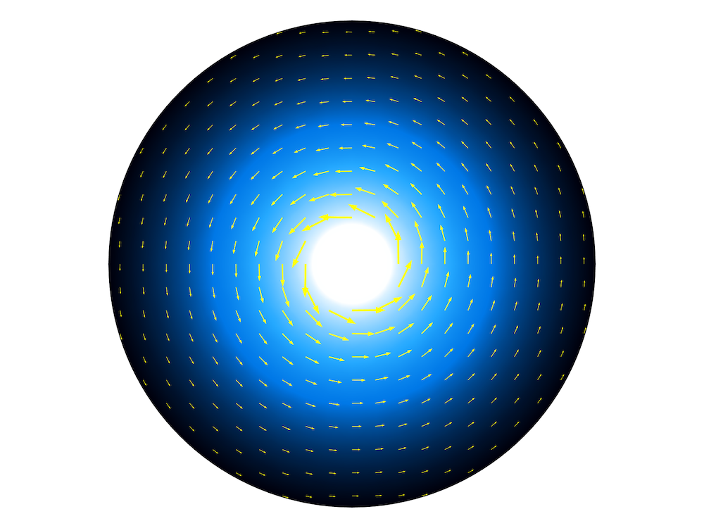
A coaxial cable cross section model. The surface plot shows the electric field norm and the arrow plot shows the magnetic field.
Frequency Domain
The Frequency Domain study step computes the near-field distribution, input impedance, and S-parameters with the Port and Lumped Port features, as well as the far-field radiation pattern with a Far-Field Domain feature.
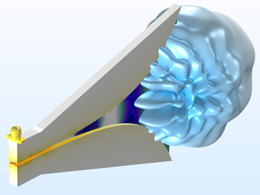
A double-ridged horn antenna for wideband antenna applications. The far-field radiation pattern and z-component of the electric field in the tapered slot are visualized at 6 GHz. The horn is removed to show the interior doubled-ridged structure.
Boundary Mode Analysis and Frequency Domain
When the cross-sectional shape of a waveguide is neither circular or rectangular, there is no known analytical solution to define the mode field in order to excite and terminate the end of the waveguide. A boundary mode analysis studies the eigenvalues on the port boundary to find the resonant mode and maps the solution to the port, while the frequency domain study step runs sequentially to compute the S-parameters and field distribution. This study combination is applicable to transmission lines, such as microstrip lines, strip lines, and coaxial lines with an arbitrary input impedance value.
In the model wizard, choose Boundary Mode Analysis in Preset Studies for Selected Physics Interfaces, and the combination of Boundary Mode Analysis and Frequency Domain studies will be added under the Study node.
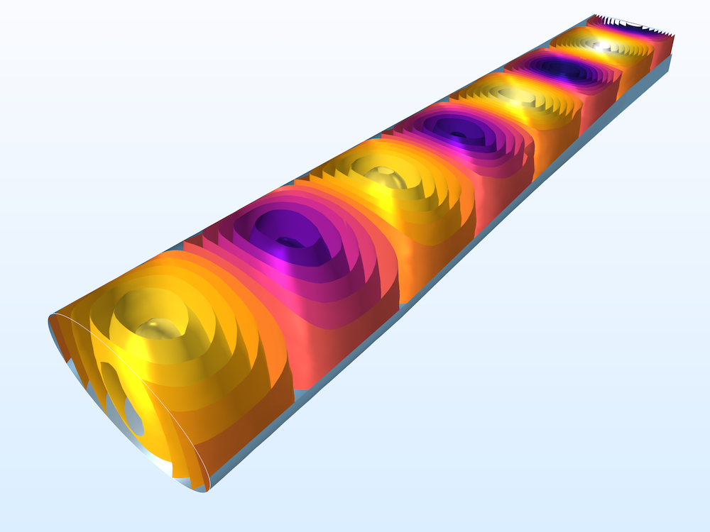
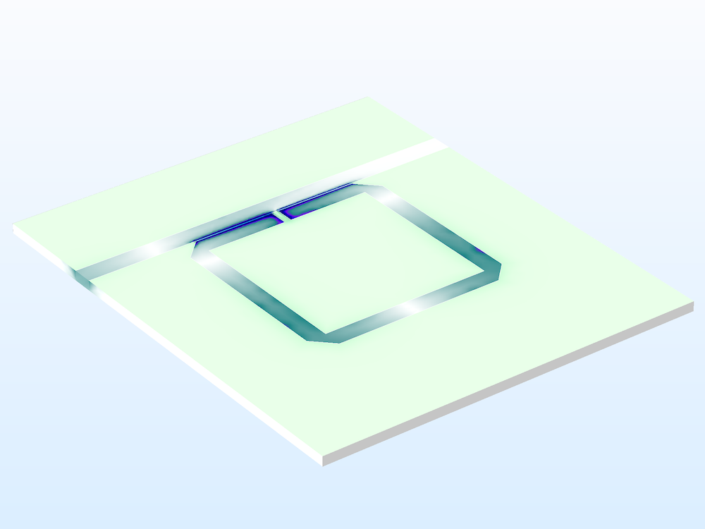
Left: A waveguide adapter utilizing the Boundary Mode Analysis study step. The x-component of the electric field in the waveguide is visualized using an isosurface plot. Contour plots of the electric field norm on the port boundaries are included. Right: A split ring resonator notch filter. The electric field norm of the circuit board is plotted.
Eigenfrequency
When the resonant frequencies of a device are of interest, use the Eigenfrequency study step with the Electromagnetic Wave, Frequency Domain physics interface. When the model presents a loss, it can be addressed using a physics feature such as the Impedance boundary condition. This study step also calculates the Q factor of the device.
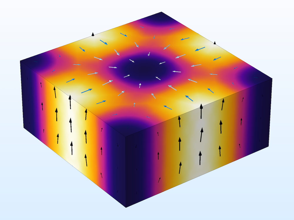
A cavity resonator model computes the resonant frequencies and Q factors.
Eigenfrequency and Frequency Domain, Modal
The Frequency Domain, Modal method is a model order reduction (MOR) technique and is suitable for computing frequency responses with a very fine resolution when the given model structure is expected to present multiple resonances. Compared to the traditional discrete frequency-domain analysis, this study step can provide a computation time for bandpass-type filter devices that is an order of magnitude faster when the frequency step is very small in the frequency sweep.
In the model wizard, choose Frequency Domain, Modal in Preset Studies for Selected Physics Interfaces and the combination of Eigenfrequency and Frequency Domain, Modal will be added under the Study node. Once the Eigenfrequency study step finds multiple resonances in a device, the Frequency Domain, Modal study runs sequentially to expand the obtained solutions in order to find the frequency responses.
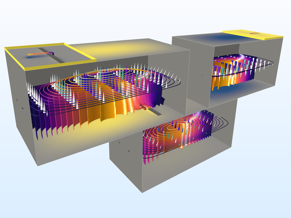
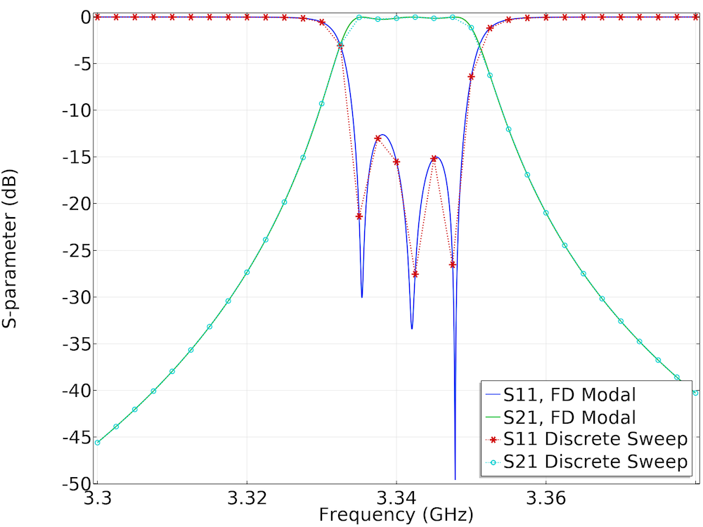
Left: A cascaded cavity filter provides bandpass frequency responses. Surface plots of the electric field norm, an arrow plot of the electric field, as well as contour and isosurface plots of the electric field norm are shown in the figure. Right: S-parameter comparison between the Frequency Domain, Modal study and a regular sweep of the Frequency Domain study.
Adaptive Frequency Sweep
The Adaptive Frequency Sweep study step utilizes asymptotic waveform evaluation (AWE), which is another MOR technique used in the RF Module. Based on the scalar expression that you expect to be plotted as a slowly varying curve, this study can find frequency responses faster than the conventional discrete frequency sweep with a fine frequency resolution.
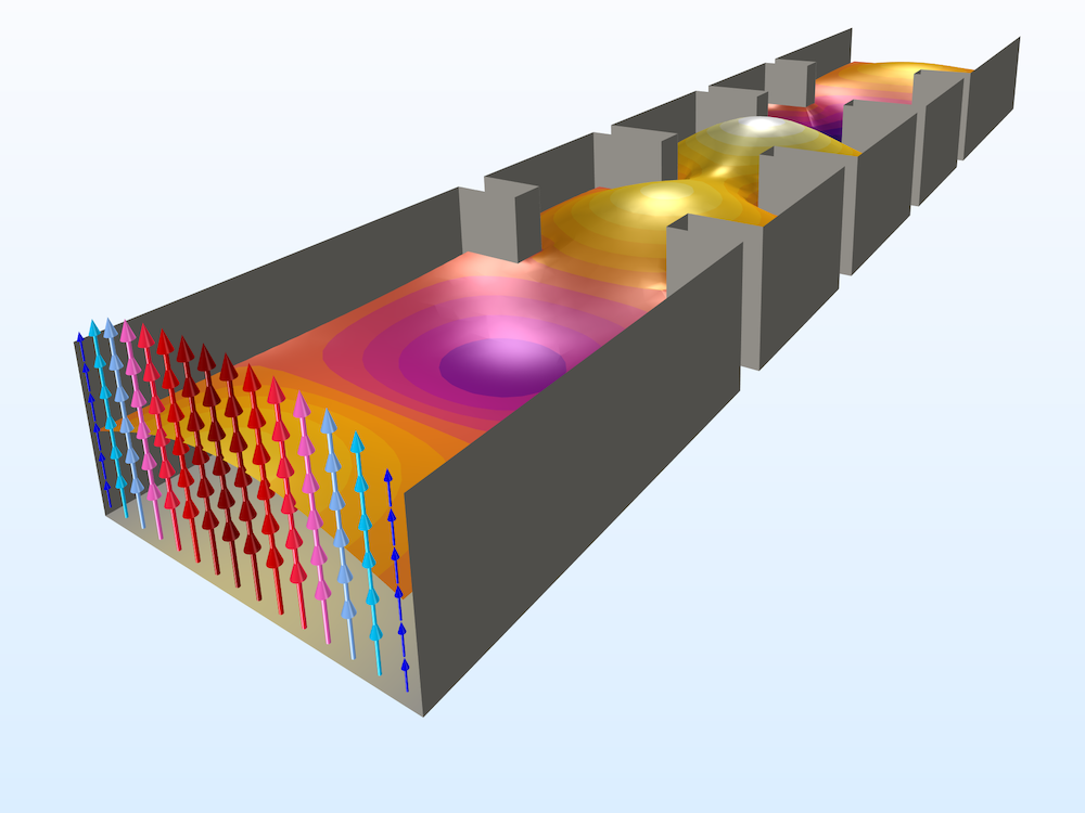
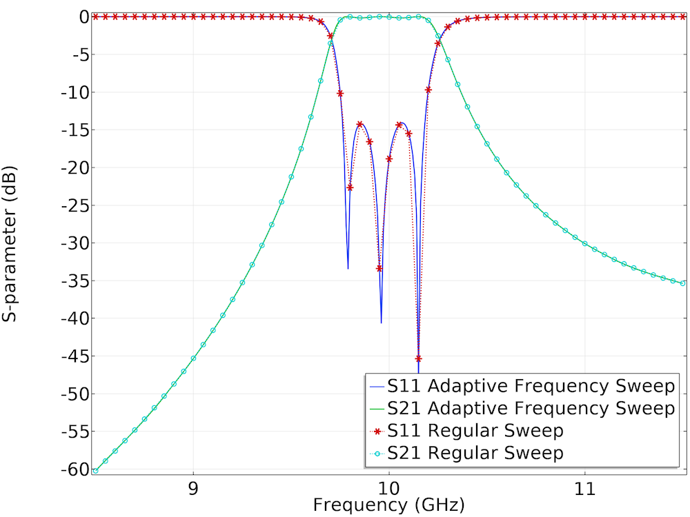
Left: Learn how to make a fast adaptive frequency sweep simulation through a waveguide iris filter. Right: S-parameter comparison between the Frequency Domain, Modal study and a regular sweep of the Frequency Domain study.
Frequency Domain and Frequency to Time FFT
The major point of interest in the Frequency Domain study lies in characterizing a device in terms of S-parameters in the frequency domain. However, the solutions are not limited to the original computational domain: The domain can be transformed into a time domain through frequency-to-time Fourier transform (FFT).
The time domain results describe the bandpass impulse response of the device, and the port voltage fluctuates as a function of time when the signal encounters an impedance mismatch and physical discontinuity. The location of discontinuity can be estimated along the signal path. Note that the FFT takes only dependent variables.
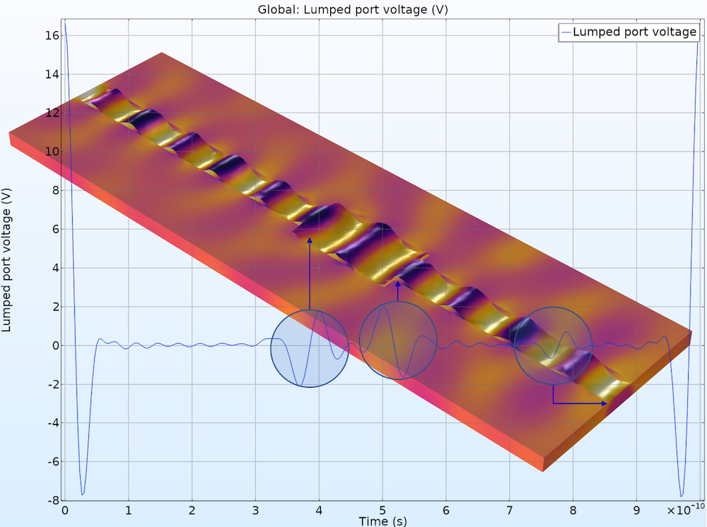
A microstrip line discontinuity study finds the cause of signal distortion using a TDR analysis.
Multiphysics with Heat Transfer
Special types of preset studies are available with predefined Microwave Heating study or by combining the Electromagnetic Waves, Frequency Domain interface with one of the heat transfer physics interfaces via the Electromagnetic Heating interface in the Multiphysics node, including:
- Frequency-Transient
- Frequency-Stationary
- Sequential Frequency-Stationary (one-way coupled electromagnetic heating)
- Sequential Frequency-Transient (one-way coupled electromagnetic heating)
Frequency-Transient
The objective of the analysis is to measure the loss of a device in the frequency domain and compute the temperature rise in the time domain. The Frequency-Transient study solves Maxwell’s equations in the frequency domain and implicitly assumes that all material properties used to solve Maxwell’s equations are constant over a single period of oscillation of the electromagnetic wave, while the heat transfer equation is solved transiently. The electromagnetic fields are only recomputed when the material properties have changed significantly, as determined by a criterion involving the relative tolerance of the time-dependent solver.
Frequency-Stationary
A Frequency-Stationary study solves Maxwell’s equations in the frequency domain and the heat transfer equation in the Stationary study step, assuming that all of the transient variations have been saturated. With this study, the steady-state temperature distribution can be obtained.
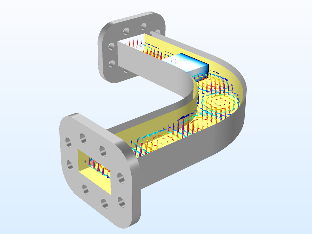
An RF heating model that includes both Frequency-Transient and Frequency-Stationary studies.
Sequential Frequency-Stationary
This one-way coupled electromagnetic heating study is used for stationary electromagnetic heating computations where the model is one-way coupled, as the stationary heat transfer equation depends on the electromagnetic heat source, but the electromagnetic analysis doesn’t depend on the temperature.
The study consists of two steps: a Frequency Domain study step, solving for the electromagnetic field distribution and loss, followed by a Stationary study step, solving for the temperature distribution.
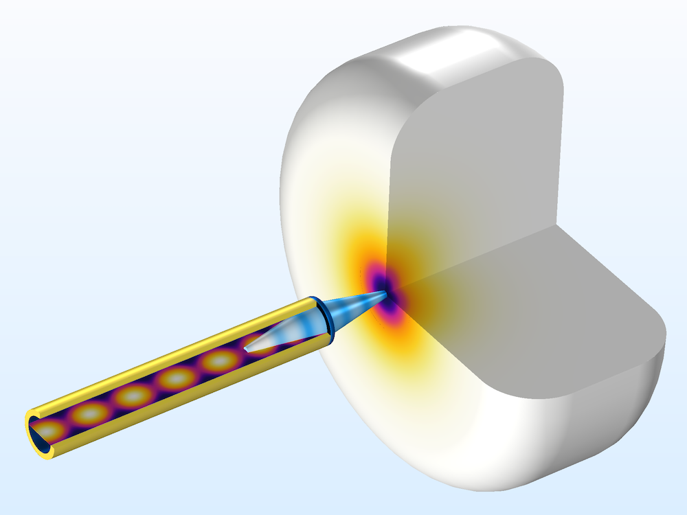
A skin cancer diagnosis tool model computes the maximum temperature rise in a phantom geometry.
Sequential Frequency-Transient
Another one-way coupled electromagnetic heating study is used for time-dependent electromagnetic heating computations where the model is one-way coupled, as the transient heat transfer equation depends on the electromagnetic heat source, but the electromagnetic analysis doesn’t depend on the temperature. The study consists of two steps: a Frequency Domain study step, solving for the electromagnetic field distribution, followed by a Time Dependent study step, solving for the temperature distribution.
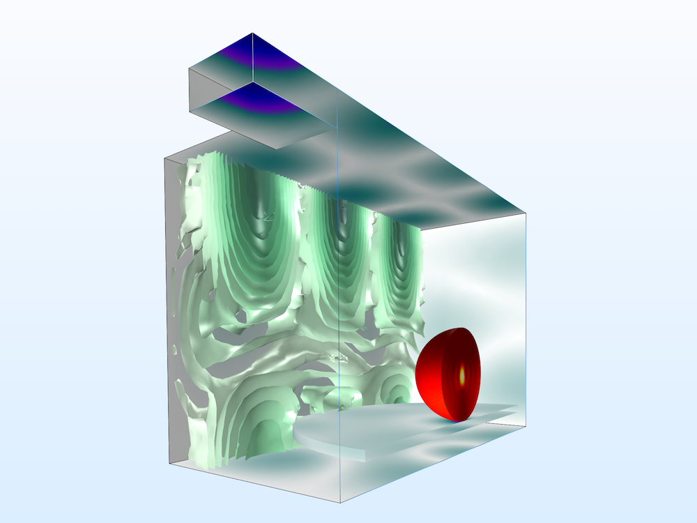
The temperature variation in a microwave oven model is observed over time.
Electromagnetic Waves, Transient
The Electromagnetic Waves, Transient interface is well suited for studying nonlinear electromagnetic wave behaviors; time-domain reflectometry; and special types of constitutive relations, such as the Drude-Lorentz dispersion model.
Time Dependent
Nonlinear Material Properties
Nonlinear material properties are defined using a remanent electric displacement relation with the solution obtained.
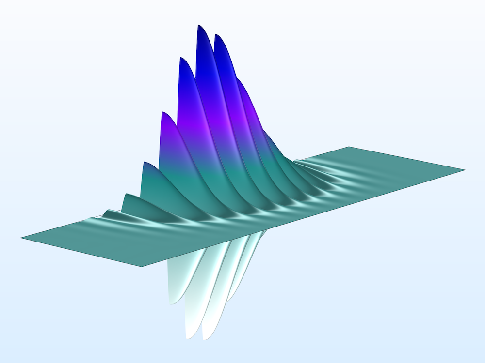
A second harmonic generation model using nonlinear material properties.
Drude–Lorentz Dispersion Model
When solving the full time-dependent wave equation in a dispersive medium, the polarization can be expressed as a sum of the Drude–Lorentz resonant terms. Each Drude–Lorentz polarization field is solved using an ordinary differential equation (ODE) driven by the electric field.
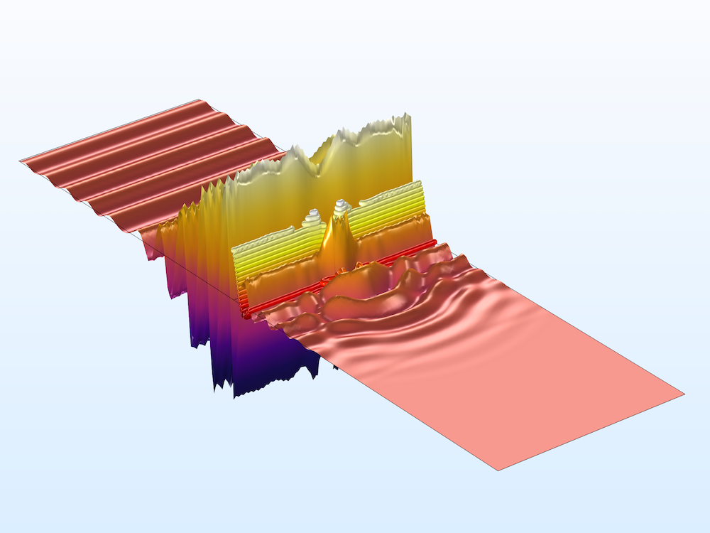
A tutorial model addressing Drude–Lorentz media.
Time-Domain Reflectometry
In signal integrity (SI) applications, time-domain reflectometry (TDR) is a useful technique for analyzing the discontinuity in a signal path by observing the reflected signal strength. The reflected signal distorts the input pulse mainly by impedance mismatch if there is no external noise source, crosstalk, or undesired coupling.
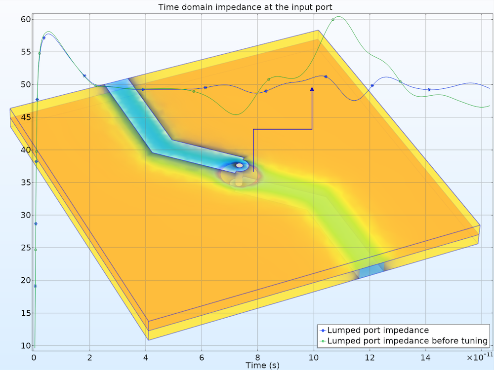
A high-speed interconnect is designed with the TDR method.
Time Dependent with FFT
A wideband antenna study, such as an S-parameter and/or far-field pattern analysis, can be obtained by performing a transient response analysis and a time-to-frequency fast Fourier transform (FFT). This model runs a time-dependent study first and then transforms the dependent variable, the magnetic vector potential A, and a voltage signal at a lumped port from the time domain to the frequency domain. S-parameters and the far-field radiation data are generated from the frequency-domain data. The computed S-parameters show two resonances in the given frequency range, as expected for this dual-band antenna design.
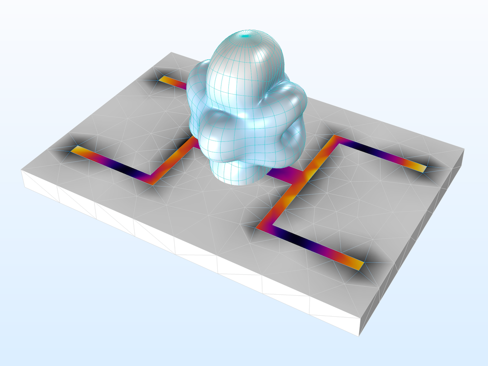
A transient analysis of a dual-band printed strip antenna. The wideband far-field radiation and S-parameters are computed in the frequency domain.
Eigenfrequency and Time Dependent, Modal
The combination of the Eigenfrequency and Time Dependent, Modal studies is also available when calculating the system response to a sinusoidal input signal around the dominant resonant frequency.
Electromagnetic Waves, Time Explicit
The Electromagnetic Waves, Time Explicit interface models time-dependent electromagnetic wave propagation in linear media. The sources can be in the form of volumetric, electric, or magnetic currents; electric surface currents, or fields on boundaries. Lumped ports on exterior boundaries are also available.
This physics interface solves two first-order partial differential equations (PDEs), Faraday’s law and Maxwell–Ampère’s law, for the electric and magnetic fields using the time-explicit discontinuous Galerkin method.
Time Dependent with FFT
A wideband radar cross section (RCS) model is analyzed using the scattered field formulation. After performing the time-dependent study and the FFT, only the relative field and postprocessing variables related to the far-field analysis are available in the frequency domain, since the FFT takes only dependent variables. Other postprocessing variables are only valid in the time domain and can be accessed via stored solutions.
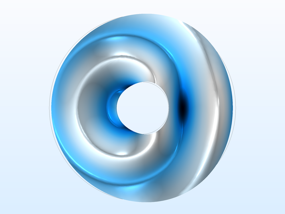
The total field is visualized in the wideband RCS model. The total field is the sum of the relative and background fields.
Transmission Line
The Transmission Line interface is used to study the propagation of waves along one-dimensional (1D) transmission lines. The interface solves the time-harmonic transmission line equation for the electric potential. Transmission line circuits, such as filters and couplers, can be designed very quickly using this physics interface, but it does not account for the coupling between adjacent lines.
Frequency Domain
The Frequency Domain study computes the electric potential distribution along a transmission line and S-parameters with Lumped Port features.

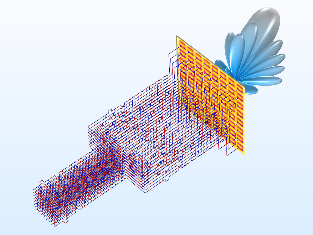
Left: A transmission line Wilkinson power divider is much simpler for a numerical analysis than the full 3D wave equation model. Right: A Butler matrix feed network can be extended to have 64 input channels and 64 output channels.
Study Settings for Managing Lean Solutions
Store Fields in Output Settings Feature
In the Values of Dependent Variables section in each study step, the Store fields in output settings feature lets you define the boundary and domain selections on which you save the solutions. If the model performs a frequency sweep with a very fine frequency resolution and only the S-parameter calculation is important, we don’t have to store the results for the entire simulation domain, but only those on the Port or Lumped Port boundaries. By choosing only the selected portion in the simulation domain, you can manage the file size of the simulation model.
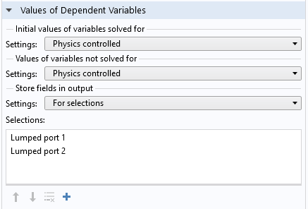
Add explicit selections where you want to save the results.
Combine Solutions Feature
The Combine Solutions feature is available in the Context menu of the Study node. You can either include or exclude this feature according to user-defined if conditions. This is especially useful after a Time to Frequency FFT study in order to exclude the noise-sensitive frequency range.
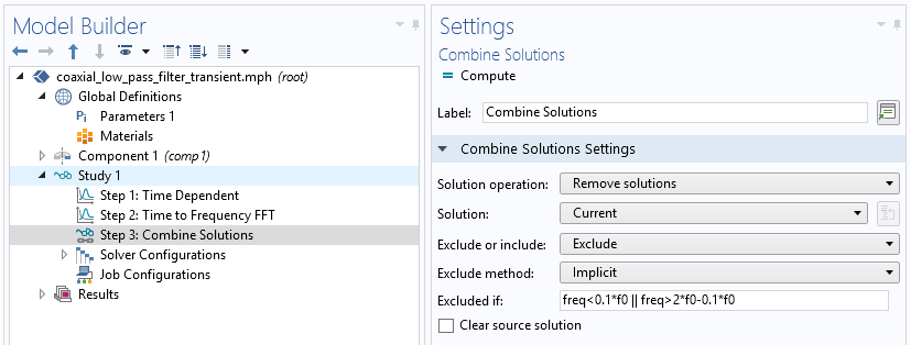
You can add the Combine Solutions feature after other study steps to filter out undesirable results.
Concluding Remarks on Using the Interfaces and Studies in the RF Module
The variety of physics interfaces that support multiple study steps in the RF Module help engineers and researchers design not only conventional passive devices, such as filters, couplers, power dividers, waveguides, microstrip lines, and coplanar waveguide structures, but also applications for 5G, IoT, and satellite communication.
You can walk through the usage of physics interfaces and study steps in the RF Module Application Gallery, where you can download model files as well as step-by-step modeling instructions.
Learn more about the specialized features for modeling RF devices and components:




Comments (0)