Fundamentals of Modeling Moving Parts for Resistive and Capacitive Devices
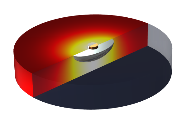
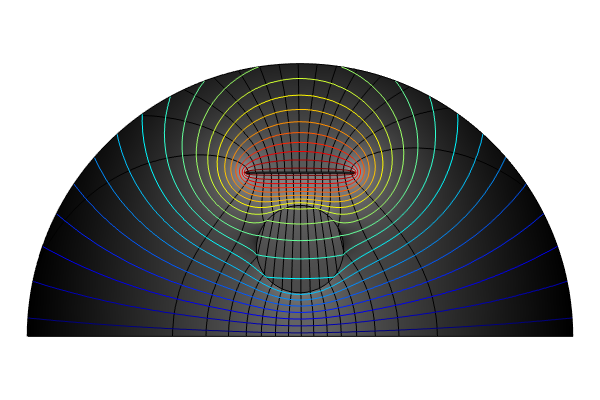
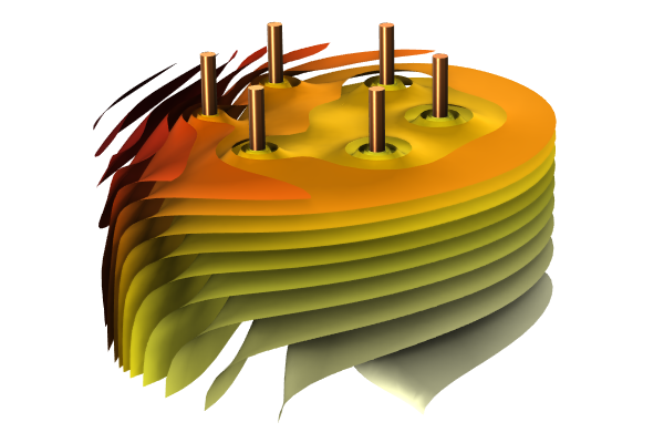
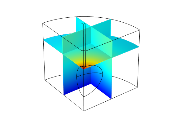
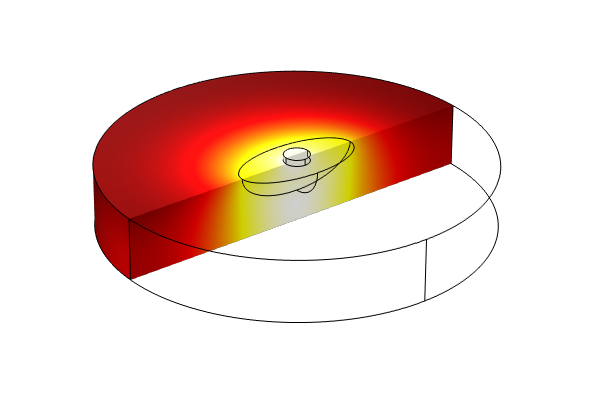
In the final part of our 10-part course, which gives an introduction to modeling resistive and capacitive devices, you will learn about modeling moving parts. The example we use throughout the lecture is a variation of a model worked with previously in the course that involves Joule heating. The geometry consists of a part with an inclusion in it and an electrode sitting on top of the inclusion at the center, with the electrode being the part moved around.
After building the geometry, we discuss how and why the use of the Form Assembly geometry finalization method, along with Identity Boundary Pairs, are required in order to simulate this movement. To ensure continuity of fields, such as the electric current across the pair boundaries, we add a Continuity node from the Pairs menu. At that time, we also introduce you to the various types of features you can apply to boundary pairs under the Electric Currents interface.
We then continue with setting up, computing, and verifying the electrical part of our model before addressing the heat transfer part of our model, wherein we similarly add a Continuity node to enforce continuity of the fields, such as the temperature and heat flux across the pair boundaries. We then introduce you to Fallback Features and discuss how and when you can add these features to a Continuity node. Upon computing the model, we perform additional postprocessing to verify our results for the heat transfer. Stationary studies have been computed thus far up to this point.
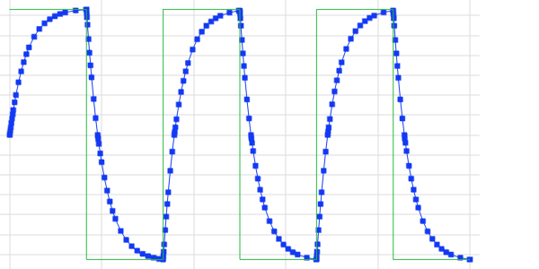
Now that the preparatory steps for simulating movement have been completed, we can model the copper electrode moving around over time using the Moving Mesh capabilities, such as the Prescribed Deformation feature and by adding a new Time Dependent study. We also briefly discuss the selection of frames for visualizing the movement.
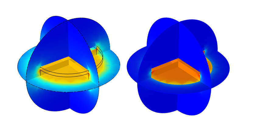
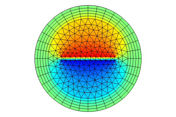
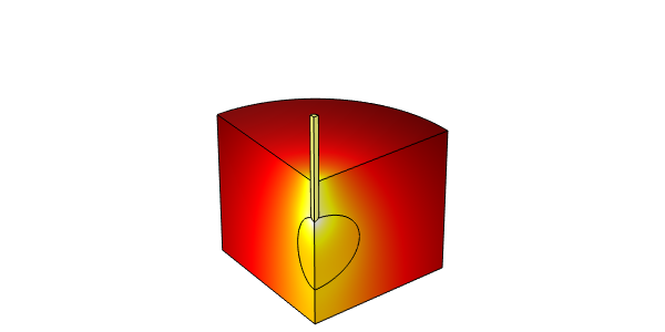
Lastly, we end with demonstrating how to model a different kind of motion, this time where the electrode comes into contact and presses into the inclusion material. This is accomplished through adding the Solid Mechanics interface, modifying the geometry so the parts start out of contact, defining a Contact Pair, modifying the mesh to minimize the number of elements in the geometry except where needed, defining and then adding a Ramp function to the Prescribed Deformation feature, and finally adding a Contact feature to the Solid Mechanics interface.
Submit feedback about this page or contact support here.

