
Acoustic-structure interaction (ASI) problems require modeling elastic waves in solids, pressure waves in fluids, and the interaction between the two. Uses of ASI include devices that generate, scatter, transmit, or receive sound and mechanical systems for sound distribution, insulation, or noise cancellation. These acoustic systems usually involve fluids and solid parts, and to predict their behavior, it’s important to capture what happens at the fluid-solid interfacing boundaries. Here, we discuss how to solve ASI problems in the COMSOL Multiphysics® software.
Available Physics Interfaces for Acoustic-Structure Interaction Analysis
Acoustic behavior in different types of materials is described by different governing equations. In COMSOL Multiphysics, this means applying different physics to domains comprising different types of materials. Elastic waves in solids, also called solid vibrations, are a subset of structural mechanics and are therefore modeled using a structural mechanics physics interface. Among the available interfaces for structural analysis, the ones most often used for vibrations analysis are Solid Mechanics, Shell, and Membrane. The Multibody Dynamics and Rotordynamics interfaces may also be used to compute noise radiation by vibrations in a complex mechanical system consisting of rigid or flexible components connected via joints or by vibrations in a rotating machine, like a rotor or motor.
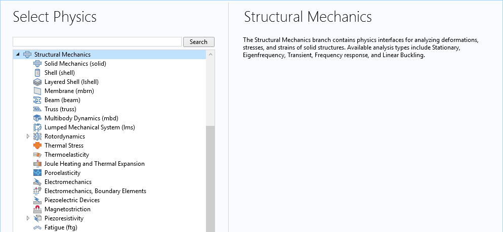
Available physics interfaces for structural analysis.
You have a few more options when it comes to modeling acoustics in fluids. As of COMSOL Multiphysics version 5.4, there are about 20 physics interfaces available in the Acoustics Module for waves in fluids based on different assumptions made for different fluid conditions. They are grouped into five branches:
- Pressure Acoustics
- Pressure waves in fluid domains outside of the viscous boundary layers and at quiescent background conditions
- Thermoviscous Acoustics
- Detailed modeling of acoustics, including the boundary layer near walls, where viscous losses and thermal conduction cannot be neglected
- Aeroacoustics
- Acoustic variations in the presence of a stationary background mean flow, also known as convected acoustics
- Ultrasound
- Propagation of acoustic signals over large distances relative to the wavelength using the discontinuous Galerkin method
- Geometrical Acoustics
- High-frequency acoustics, where the acoustic wavelength is much smaller than the characteristic geometric features
In general, you can manually select an interface for elastic waves in solids and an interface for pressure waves in fluids and then define the couplings between them. An easier and more convenient way is to use one of the built-in multiphysics interfaces that have predefined couplings between solids and fluids. Most of these multiphysics interfaces are included in the sixth branch of the Acoustics Module, the Acoustic-Structure Interaction branch, where pressure acoustics physics are coupled to structural mechanics. There are a couple more in the Thermoviscous Acoustics branch that couple thermoviscous acoustics to structural mechanics. The image below shows the available multiphysics interfaces for ASI applications.
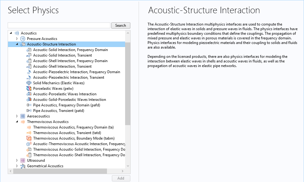
Available multiphysics interfaces for ASI analysis.
We will first discuss how to use the predefined multiphysics interfaces for acoustic-structure interaction analysis, then explain how to manually add interfaces and define couplings when a predefined multiphysics feature is not available between the selected interfaces.
Modeling Acoustic-Structure Interaction Using the Predefined Multiphysics Interfaces
The predefined multiphysics interfaces allow you to include a mixture of material types in the model, such as fluids, linear elastic materials, porous media, and piezoelectric devices. In addition, the coupling between different materials is automatically done for you. Select a specific interface based on what types of materials are included in the model and whether you want to solve the problem in the frequency domain or time domain.
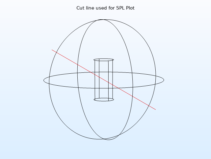
Let’s use the Acoustic-Structure Interaction tutorial as an example. We want to model the interaction of an incident plane wave with an elastic aluminum cylinder in water. The sound will cause movement of the elastic cylinder, which in turn will radiate new sound waves to the fluid. Thus, full two-way coupling between the acoustic medium (water) and the cylinder is required to realistically simulate this situation. The figure below illustrates the aluminum cylinder immersed in water. The incident wave is at 60 kHz (in the ultrasound region). The cylinder is 2 cm in height and 1 cm in diameter. The water’s acoustic domain is truncated as a sphere with a reasonably large diameter.
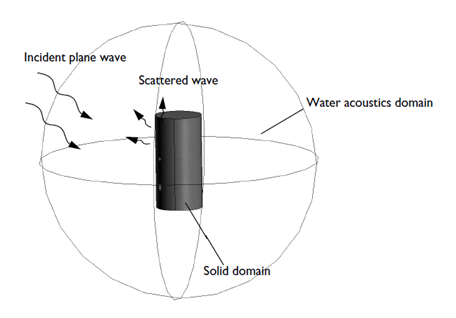
Geometric setup of an aluminum cylinder immersed in water.
Here, we have two types of materials, a fluid (water) and a linear elastic material (aluminum), and we want to run a frequency-domain analysis to get the steady-state time-harmonic solution of the total acoustic field. To set up the model, we choose the Acoustic-Solid Interaction, Frequency Domain multiphysics interface. This interface involves two single interfaces: Solid Mechanics and Pressure Acoustics, Frequency Domain. It also defines an Acoustic-Structure Boundary coupling feature under the Multiphysics node.
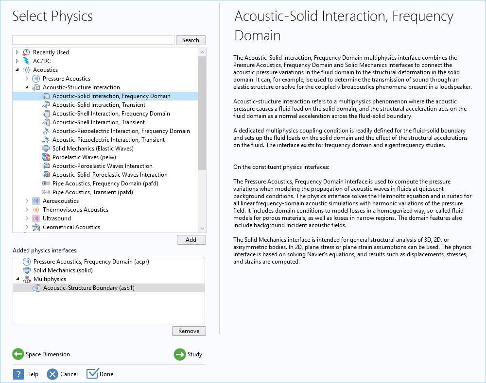
The predefined Acoustic-Solid Interaction, Frequency Domain multiphysics interface involves the Solid Mechanics and Pressure Acoustics, Frequency Domain interfaces and defines an Acoustic-Structure Boundary coupling feature under the Multiphysics node.
An important step in setting up the model is to edit domain selections for each interface to make sure they are applied to the correct domains. By default, COMSOL Multiphysics includes all physical domains in every interface, so we need to go through each one and remove domains that are not applicable. In this example, remove the inner cylinder from the Pressure Acoustics, Frequency Domain node so it is only applied to the water domain. Similarly, remove the outer spherical water domain from the Solid Mechanics feature so it is only applied to the solid cylinder. Once we have completed this step, COMSOL Multiphysics is able to detect the interfaces between the pressure acoustics and solid mechanics and apply the coupling on those boundaries. We are able to inspect and view the coupling surfaces in the Acoustic-Structure Boundary node under Multiphysics.
Example model showing the automatic Acoustic-Structure Boundary multiphysics coupling.
The acoustic source for this example is an incident plane wave on the outer spherical perimeter of the water domain, representing an incoming sound wave. To do so, we add a Spherical Wave Radiation boundary node and apply it to the spherical surfaces and then add an Incident Pressure Field subnode to specify the amplitude and wave direction of the plane wave. This radiation condition allows an outgoing spherical wave to leave the modeling domain with minimal reflections. This boundary condition is useful when the surroundings are only a continuation of the domain.
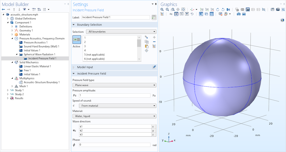
An incident plane wave is specified on the outer spherical perimeter of the water domain to represent an incoming sound wave.
We do not need to do anything to the Solid Mechanics interface. The default settings will work in this case, and no constraints need to be applied to this pure vibration problem. Usually, how solids are supported in space needs to be reflected in the model. For instance, any parts of the solids that are fixed, or restricted to move in certain directions, need to be modeled. These constraints will affect the vibration behavior of the solids and therefore cannot be neglected. For this conceptual example, though, we will stay simple and use the default.
Let’s move to the meshing part. The rule of thumb for meshing wave problems is to apply at least five to six second-order mesh elements per local wavelength in order to resolve waves. Both the pressure acoustics and solid mechanics physics use second-order Lagrange elements by default, so we need to set the maximum element size to about one-fifth of the wavelength or smaller. For this example, we use one-sixth of the wavelength in water to define the maximum element size. This also ensures that the mesh is able to resolve elastic waves in the solid, since they have larger wavelengths than those in water.
In case the model includes very soft elastic materials that have a slower speed of sound than that of the fluid, use the speed of sound in the solid to estimate the maximum element size that should be applied in the solid domains. COMSOL Multiphysics calculates speeds of sound in solids automatically. For example, if the Solid Mechanics interface is used in the model, the pressure wave speed is calculated and stored in the variable solid.cp and shear wave speed in solid.cs. You can use the slower shear wave speed to set up a starting mesh. When we need to resolve surface wave modes that usually travel even slower than the shear wave mode, the speed of the slowest surface wave of interest should be adopted to determine the size of the mesh used to discretize the solid domains.

Manually setting the mesh element sizes to ensure waves are well resolved.
The animation below shows the total acoustic pressure in water on a plane right behind the cylinder and the deformation of the aluminum cylinder.
Total acoustic pressure in water on a plane and deformation of the aluminum cylinder.
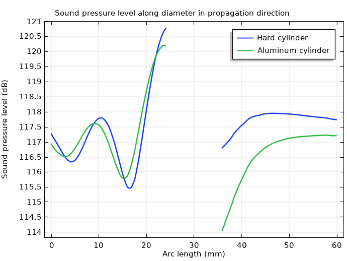
The plot below shows a comparison between the full aluminum solid model and a simpler model where the solid interface is regarded as a hard wall. Near the cylinder wall, the plot demonstrates a higher sound pressure level on both the upstream and downstream sides for the hard-wall case than for the aluminum model, which shows that the mechanical properties of the metal object have an impact on the acoustic signature.
Sound pressure level on impact and on the shadow side of the cylinder.
Coupling Methodology for ASI
This example uses the implemented Acoustic-Structure Boundary coupling that includes the fluid load on the structure and the structural acceleration as experienced by the fluid. Mathematically, the condition on the boundaries reads
where utt is the structural acceleration, nis the surface normal, pt is the total acoustic pressure, qd is the acoustic dipole domain source (if applicable), and FA is the load (force per unit area) experienced by the structure.
The Acoustic-Structure Boundary coupling can be used to couple a pressure acoustics model to any structural component. This includes the acoustics interfaces based on both the finite element method (FEM) and the boundary element method (BEM). The feature couples to the Solid Mechanics, Shell, Membrane, and Multibody Dynamics interfaces.
For thin interior structures (like shells and membranes) with fluid on both sides, a slit is added to the pressure variable (it is made discontinuous), and we make sure to couple the up and down sides. On interior boundaries, the condition reads
such that the acoustic load is given by the pressure drop across the thin structure. The up and down subscripts refer to the two sides of the interior boundary.
Predefined Coupling Features
When adding a predefined multiphysics interface to the model, both the contributing physics interfaces and the multiphysics couplings are added to the Model Builder. Sometimes, it is preferable to build a model sequentially, adding one physics interface at a time. Once that’s done, we need to add the coupling manually. The Acoustics Module includes the following predefined acoustic-structure coupling features:
- Acoustic-Structure Boundary
- Thermoviscous Acoustic-Structure Boundary
- Aeroacoustic-Structure Boundary
- Acoustic-Porous Boundary
- Porous-Structure Boundary
These features are used in the predefined multiphysics interfaces, although they can also be used to couple physics interfaces when a predefined multiphysics interface is not available. For example, the Acoustic-Structure Boundary feature can be used to couple a BEM-based pressure acoustics model to a structural component, although there is not a predefined multiphysics interface that couples BEM pressure acoustics with structural mechanics.
The Thermoviscous Acoustic-Structure Boundary coupling and the Aeroacoustic-Structure Boundary coupling are used to couple a thermoviscous acoustics model or an aeroacoustics model (it only applies to the linearized Navier–Stokes interfaces) to a structural model including the Solid Mechanics, Shell, Membrane, and Multibody Dynamics interfaces. For both couplings, continuity in the velocity field and surface stress is prescribed, since the thermoviscous acoustics and the linearized Navier–Stokes models both resolve acoustics in the boundary layer. (See the Vibrating Micromirror with Viscous and Thermal Damping and Coriolis Flowmeter: FSI Simulation in the Frequency Domain tutorial models.)
The Acoustic-Porous Boundary coupling is used to couple a pressure acoustics interface to a porous material (Biot’s model) domain modeled with the Poroelastic Waves interface. This also includes both the FEM-based and BEM-based acoustics interfaces. The feature applies continuity of the fluid pressure on the boundaries, a boundary load from the fluid pressure on the elastic waves in the porous material, and a normal acceleration of the porous matrix skeleton experienced by the fluid.
The Porous-Structure Boundary coupling is used to couple a porous domain (Biot’s model) from the Poroelastic Waves interface to the Solid Mechanics, Shell, Membrane, or Multibody Dynamics interface. At the solid-porous boundaries, continuity of the displacement field is applied.
Modeling ASI by Manually Adding Physics Interfaces and Couplings
When a predefined multiphysics interface is not available — or when a new physics interface is added to an existing model and needs to couple to an existing interface — we must manually add the coupling to model the interaction between the interfaces. Whenever a predefined coupling feature is available for the added interfaces, a Multiphysics node will automatically be added to the Model Builder. We then simply right-click the Multiphysics node and choose the coupling from the selection list.
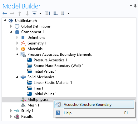
The predefined Acoustic-Structure Boundary feature is available for coupling the Pressure Acoustics, Boundary Elements interface to the Solid Mechanics interface.
Typically, we are able to solve an ASI problem using the predefined coupling features. However, sometimes a predefined coupling is not available; for example, when a lumped circuit model is used to describe the mechanical behavior of a device and a two-way coupling between the SPICE model and an acoustic model is desirable. In those cases, we have to manually add the coupling in the physics interfaces.
Example: Modeling a Lumped Receiver
As an example, let’s model a Knowles ED-23146 balanced armature receiver (a type of miniature loudspeaker). The device is connected to a test setup that represents the receiver in a behind-the-ear hearing aid, which drives an ear canal with a deeply inserted ear mold via a long narrow tube. The receiver is modeled as an electric SPICE circuit using the Electrical Circuit interface and connected to the finite element domain at the tube inlet. The acoustics inside the tube and the coupler are modeled using the Pressure Acoustics, Frequency Domain interface.

Schematic representation of the modeled system consisting of receiver, tube, coupler, and measurement microphone. The blue domains are modeled using FEM-based pressure acoustics physics interface and the receiver is modeled using a lumped spice network.
In the lumped model used for the receiver, the current at the output corresponds to a volume flow (m3/s), while the voltage over the output terminals corresponds to the pressure (Pa), as measured at the outlet of the transducer.
To couple the SPICE network to the FEM-based pressure acoustics model, the average pressure over the inlet of the tube is applied as a voltage source at the outlet of the receiver in the Electrical Circuit interface, and the current at the output of the SPICE transducer model is applied as an inward normal acceleration on the inlet of the tube in the pressure acoustics model. The averaged pressure, Pin, and the inward acceleration, An, are defined as

Where intop_in() is an integration operator defined on the inlet surface of the narrow tube, p is the acoustic pressure, acpr.iomega is the complex angular frequency, and cir.V2_i is the current at the output of the SPICE receiver.
Manually coupling the SPICE network to the FEM-based pressure acoustics model.
Solving Large ASI Models
Per default, COMSOL Multiphysics uses a fully coupled direct solver for ASI models. If the direct solver runs out of memory, a simple first approach is to enable and use one of the iterative solver suggestions. A good starting point for this is to right-click the study node and select Show Default Solver, then expand the Solver Configuration tree under Stationary Solver or Time-Dependent Solver. Predefined iterative solver suggestions are automatically generated. As shown in the image below, two iterative solvers are suggested and disabled. To turn one on, right-click the solver and select Enable (or press F4).
The first suggestion (GMRES with GMG) uses the general minimum residual (GMRES) iterative solver with a geometric multigrid (GMG) preconditioner. This method is typically faster than the direct solver and uses less memory for large 3D models. The second suggestion (FGMRES with GMG) uses the flexible GMRES (FGMRES) iterative solver with a GMG preconditioner. This method is more robust than GMRES, especially for problems that exhibit sharp resonances. If the GMRES suggestion does not converge, try the FGMRES suggestion instead.
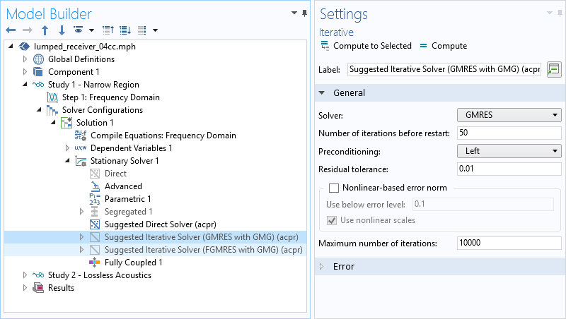
Predefined iterative solver suggestions are automatically generated by the default solver for 3D acoustics models.
Another strategy for solving large acoustic-structure problems involves solving the system in a segregated way. That is, the system is not solved fully coupled in one step; instead, iterations are used to solve one physics interface at a time.
To set up such a solver, we right-click on the Stationary Solver step and select Segregated. In the first Segregated Step, solve for the structurally dependent variables (displacement). We set up a second segregated step to select the pressure-dependent variable. Under each step, choose the solver for the single physics interface problem. For example, when only a small structural domain is included, use an iterative multigrid approach for the acoustics and a direct solver for the structure.
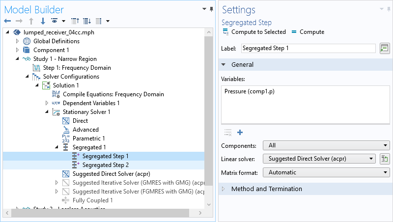
Solving large acoustic-structure problems in a segregated way.
This strategy is only readily applicable when the coupling between the solid and the acoustic domain is done via Neumann conditions; this is the case for all models where the acoustic domain uses the Pressure Acoustics interface. For example, in models with thermoacoustic-structure interaction, the coupling is based on a Dirichlet condition (a pointwise constraint) and requires reformulating the continuity condition using weak constraints. This approach also does not work for models coupling piezoelectric domains, structures, and acoustics; in those cases, a fully coupled approach is necessary.
In all instances the various solver strategies and other useful suggestions are discussed in detail in the Modeling sections of the Acoustic Module User’s Guide.
Next Steps
- Learn more about acoustics modeling on the COMSOL Blog:




Comments (13)
LUIS Yoza
June 18, 2019Dear Jinlan Huang: Thanks, your applications are very interesting, I am working on trying to evaluate the interaction of ultrasound waves with a cylindrical cavity that is in a solid with ortrotropic symmetry (wood). Could indicate me some acoustic model, that could use to orient me.
best regards
Luis Yoza
Ben Isaak
June 19, 2019It’s very interesting.
Vipul Rokad
July 24, 2019Dear Jinlan Huang,
I want to develop water bubble formation in a steel sink by using piezoelectric transducer as bottom of sink. I am beginner in comsol. Could you help me to develop it.
A waiting for your reply.
Regards,
Jinlan Huang
July 24, 2019 COMSOL EmployeeHi Vipul, I will suggest you send this specific question to support@comsol.com.
Ahmed Sallam
August 14, 2019Jinlan Huang,
Can you please tell me how did you create that animation? It looks cool and I want to try doing it myself.
Thank you,
雅静 王
May 27, 2021Dear Huang:
Your animation is very interesting, but I have a question: how to create the animation only in the research state of frequency?
sincerely,
Yajing Wang
Joey Frederick
May 1, 2020Dear Jinlan, Thanks so much for this article. Excellent overview of FSI strategy, physics interfaces, and insights into the physics. Answered all my questions.
Kind Regards,
Joey Frederick
Ho Ha
May 15, 2020Dear Julian
Thanks for the great information. Is there any way to eliminate the pressure waves, and only simulate the shear waves in a tissue model in COMSOL?
Thanks!
Jinlan Huang
May 15, 2020 COMSOL EmployeeHi Ho Ha, for Frequency Domain analysis, there is really no way to separate shear wave from other wave modes unless it is the only mode being excited. For transient analysis, however, this is possible when the exciting signal is short and waves are allowed to travel enough long distance so that different wave modes are separated due to their different propagation speeds.
Dezhang Chu
September 25, 2020Dear Dr. Jinlan Huang,
I attend your Lectures on Acoustics about two months ago. It was a great help to my application. I am working on a problem on simulating the backscattering by objects in underwater acoustic application. Here are my questions:
1. How do I obtain the backscatter in the farfield since the computation domain is in the near field? Your lecture demonstrated how to get some exterior field calculation but I don’t know how to get an 1D Plot of the scattered field as a function of frequency at a set point in the exterior field.
2. How can I export the results described above, i.e. the data points of the 1D plot?
Many thanks,
Dezhang Chu
雅静 王
May 27, 2021Dear Huang:
Your animation is very interesting, but I have a question: how to create the animation only in the research state of frequency?
sincerely,
Yajing Wang
Jinlan Huang
May 28, 2021 COMSOL EmployeeHi Yajing, to create an animation from a frequency domain study, you need to set the Sequence type to Dynamic data extension at the Animation Editing section, it will then play the solution over the full acoustic cycle. Please send your further questions to support@comsol.com.
雅静 王
May 30, 2021Dear Jinlan:
Thank you so much for your response and advice, which solved my recent problem. It is so great!