
We have introduced a new interface for simulating piezoelectric devices in version 5.0 of the COMSOL Multiphysics simulation software. This interface aims to achieve several things. In this blog post, I will explain what these things are and how you can use them.
The New Piezoelectric Interface, in a Nutshell
The piezoelectric modeling interface seeks to:
- Make the modeling workflow more
- Transparent
- Flexible
- Enable you to debug the models more easily
This will allow you to successfully simulate piezoelectric devices as well as easily extend the simulation by coupling it with any other physics.
Modeling Piezoelectricity in COMSOL Multiphysics
You may already be familiar with the three different modules that can be used for simulating piezoelectric materials:
Each of these modules gives you a predefined Piezoelectric Devices interface that you can use for modeling systems that include both piezoelectric and other structural materials. The Acoustics Module offers two predefined interfaces, namely the Acoustic-Piezoelectric Interaction, Frequency Domain interface and the Acoustic-Piezoelectric Interaction, Transient interface. These two allow you to model how piezoelectric acoustic transducers interact with the fluid media surrounding them.
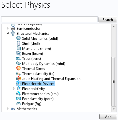
The Piezoelectric Devices interface is available in the list of structural mechanics physics interfaces.
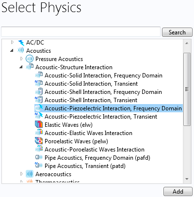
The Acoustic-Piezoelectric Interaction, Frequency Domain and the Acoustic-Piezoelectric Interaction, Transient interfaces are available in the list of acoustics physics interfaces.
These predefined multiphysics interfaces couple the relevant physics governing equations via constitutive laws or boundary conditions. Thus, they offer a good starting point for setting up more complex multiphysics problems involving piezoelectric materials. The new piezoelectric interfaces in COMSOL Multiphysics version 5.0 provide a transparent workflow to visualize the constituent physics interfaces. There is also a separate Multiphysics node that lists how the constituent physics interfaces are connected to each other.
Let’s find out how these multiphysics interfaces are structured.
Piezoelectric Devices
Upon selecting the Piezoelectric Devices multiphysics interface, you see the constituent physics: Solid Mechanics and Electrostatics. You also see the Piezoelectric Effect branch listed under the Multiphysics node, which controls the connection between Solid Mechanics and Electrostatics.
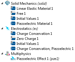
Part of the model tree showing the physics interfaces and multiphysics couplings that appear upon selecting the Piezoelectric Devices interface.
By default, all modeling domains are assumed to be made of piezoelectric material. If that is not the case, you can deselect the non-piezo structural domains from the branch Solid Mechanics > Piezoelectric Material. These domains then get automatically assigned to the Solid Mechanics > Linear Elastic Material branch. This process ensures that all parts of the geometry are marked as either piezoelectric or non-piezo structural materials and that nothing is accidentally left undefined.
Solid Mechanics Node
If you are working with other material models that are available with the Nonlinear Structural Materials Module, such as hyperelasticity, you can add that as a branch under Solid Mechanics and assign the relevant parts of your modeling geometry to this branch. The Solid Mechanics node gives us full flexibility to set up a model that involves not only piezoelectric material but also linear and nonlinear structural materials. The best part is that if these materials are geometrically touching each other, the COMSOL software will automatically take care of displacement compatibility across them.
If some parts of the model are not solid at all, like an air gap, you can deselect them in the Solid Mechanics node.
From the Solid Mechanics node, you will also assign any sort of mechanical loads and constraints to the model.
Electrostatics Node
The Electrostatics node allows you to group together all the information related to electrical inputs to the model. This would include, for example, any electrical boundary conditions such as voltage and charge sources. By default, any geometric domain that has been assigned to the Solid Mechanics > Piezoelectric Material branch also gets assigned to the Electrostatics > Charge Conservation, Piezoelectric branch. If you have any other dielectric materials in the model that are not piezoelectric, you could assign them to the Electrostatics > Charge Conservation branch.
Piezoelectric Effect Node
The Multiphysics > Piezoelectric Effect branch ensures that the structural and electrostatics equations are solved in a coupled fashion within the domains that are assigned to the Solid Mechanics > Piezoelectric Material (and also the Electrostatics > Charge Conservation, Piezoelectric) branch.
The multiphysics coupling is implemented using the well-known coupled constitutive law for piezoelectric materials. Note that the Electrostatics > Charge Conservation, Piezoelectric branch is mainly used as a placeholder for assigning geometric domains that belong to the piezoelectric material model. This helps the Multiphysics > Piezoelectric Effect branch understand whether a domain assigned to the Electrostatics interface is piezoelectric or not.
Note: For an example of working with the Piezoelectric Devices interface, check out the tutorial on modeling a Piezoelectric Shear Actuated Beam.
Adding Damping in Dynamic Analysis
It is also possible to add effects of damping or other material losses in dynamic simulations. You can do so by adding one or more of the following subnodes under the Solid Mechanics > Piezoelectric Material branch:

Damping and losses that can be added to a piezoelectric material.
| Subnode Name | When to Use the Subnode |
|---|---|
| Mechanical Damping | Allows you to add purely structural damping. Choose between using Loss Factor (in frequency domain) or Rayleigh damping (for both frequency and time domains) models. |
| Coupling Loss | Allows you to add electromechanical coupling loss. Choose between using Loss Factor (for frequency domain) or Rayleigh damping (for both frequency and time domains) models. |
| Dielectric Loss | Allows you to add dielectric or polarization loss. Choose between using Loss Factor (for frequency domain) and Dispersion (for both frequency and time domains) models. |
| Conduction Loss (Time-Harmonic) | Allows you to add electrical energy dissipation due to electrical resistance in a harmonically vibrating piezoelectric material (for frequency domain only). |
Note: For an example of adding damping to piezoelectric models, check out the tutorial on modeling a Thin Film BAW Composite Resonator.
Additional damping also takes place due to the interaction between a piezoelectric device and its surroundings. This can be modeled in greater details using the Acoustic-Piezoelectric Interaction interfaces.
Acoustic-Piezoelectric Interaction
Upon selecting one of the Acoustic-Piezoelectric Interaction interfaces, you see the constituent physics: Pressure Acoustics, Solid Mechanics and Electrostatics. You also see the Acoustic-Structure Boundary and Piezoelectric Effect branches listed under the Multiphysics node.
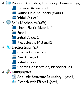
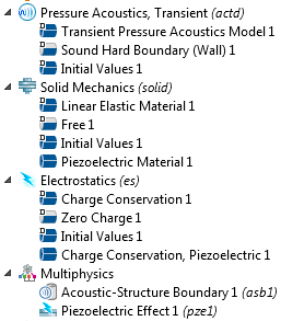
Part of the model tree showing the physics interfaces and multiphysics couplings that appear when selecting the Acoustic-Piezoelectric Interaction, Frequency Domain and the Acoustic-Piezoelectric Interaction, Transient interfaces.
By default, all modeling domains are assigned to the Pressure Acoustics interface as well as the Solid Mechanics > Piezoelectric Material and Electrostatics > Charge Conservation, Piezoelectric branches. Note that the Pressure Acoustics interface is designed to simulate acoustic waves propagating in fluid media.
Since COMSOL Multiphysics cannot know a priori which parts of the modeling geometry belong to the fluid domain and which ones are solids, you are expected to provide that information by deselecting the solid domains from the Pressure Acoustics, Frequency Domain (or Pressure Acoustics, Transient) branch and deselecting the fluid domains from the Solid Mechanics and Electrostatics branches.
Once you do that, the boundaries at the interface between the solid and fluid domains are detected and assigned to the Multiphysics > Acoustic-Structure Boundary branch. This branch controls the coupling between the Pressure Acoustics and Solid Mechanics physics interfaces. It does so by considering the acoustic pressure of the fluid to be acting as a mechanical load on the solid surfaces, while the component of the acceleration vector that is normal (perpendicular) to the same surfaces acts as a sound source that produces pressure waves in the fluid.
Note: For an example of Acoustic-Piezoelectric Interaction, check out the tutorial on modeling a Tonpilz Transducer.
Easy to Add More Physics
The transparency in the workflow as discussed above also paves the way for adding more physics and creating your own multiphysics couplings.
For example, let’s say there is some heat source within your piezoelectric device that produces nonuniform temperature distribution within the device. In order to model this, you can add another physics interface called Heat Transfer in Solids in the model tree and prescribe appropriate heat sources and sinks to find out the temperature profile. You could then add a Thermal Expansion branch under the Multiphysics node to compute additional strains in different parts of the device as a result of the temperature variation.
The Multiphysics > Thermal Expansion branch couples the Heat Transfer in Solids and the Solid Mechanics interfaces. It might also be possible that the piezoelectric material properties have a temperature dependency. You could represent these properties as functions of temperature and let the Multiphysics > Temperature Coupling branch pass on the information related to temperature distribution in the modeling geometry to the Solid Mechanics or even the Electrostatics branches, thereby producing additional multiphysics couplings.
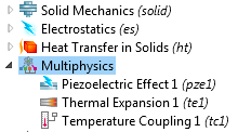
Part of the model tree showing the physics interfaces and multiphysics couplings that you can use to combine piezoelectric modeling with thermal expansion and temperature-dependent material properties.
Enable or Disable Multiphysics Couplings
Similar to adding more physics and multiphysics couplings, it is also possible to disable one or more multiphysics couplings — or even any of the physics interfaces shown in the model tree. This could be immensely helpful for debugging large and complex models.
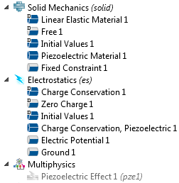
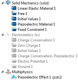
The model tree on the left shows a scenario where the Piezoelectric Effect multiphysics coupling is disabled. The model tree on the right shows a scenario where the Electrostatics physics interface is disabled.
For example, you can disable the Multiphysics > Piezoelectric Effect branch and solve for the Solid Mechanics and Electrostatics physics interfaces in an uncoupled sense. You could also solve a model by disabling either the Solid Mechanics or the Electrostatics interface.
Running such case studies could help in evaluating how the device would respond to certain inputs if there were no piezoelectric material in place. This approach could also be used to evaluate equivalent structural stiffness or equivalent capacitance of the piezoelectric material.
You could also start by adding only one of the constituent physics, say Solid Mechanics, and after performing some initial structural analysis, go ahead and add the Electrostatics physics interface to the model tree once you are ready to add the effect of a piezoelectric material.
In that case, when you add the Electrostatics physics on top of the existing Solid Mechanics physics in the model tree, the COMSOL software will automatically add the Multiphysics node. From there, you can manually add the Piezoelectric Effect branch. Note that if you take this approach of adding the constituent physics interfaces and multiphysics effect manually, you would also have to manually add the piezoelectric modeling domains to the Solid Mechanics > Piezoelectric Material, the Electrostatics > Charge Conservation, Piezoelectric, and the Multiphysics > Piezoelectric Effect branches.
In a similar fashion, you can continue to add more physics interfaces and multiphysics couplings to your model based on your needs.
Additional Resources
To learn more about modeling piezoelectric devices in the COMSOL software environment, you are encouraged to refer to these resources:
- Piezoelectric Features Overview
- Acoustics Module User’s Guide
- MEMS Module User’s Guide
- Structural Mechanics Module User’s Guide


Comments (3)
pedram sarmadi
January 23, 2016hi, I can’t find a way for adding pyroelectricity to my model. is it possible in comsol? I need to simulate electrocaloric effect.
Nebyat Weldearegay
November 8, 2018Hi, would you please inform me how can i model a cantilever beam partially immersed in liquid using comsol multi physics software?
Brianne Costa
November 12, 2018 COMSOL EmployeeHi Nebyat,
Thank you for your comment.
For questions related to your modeling, please contact our Support team.
Online Support Center: https://www.comsol.com/support
Email: support@comsol.com