
Solar-grade silicon is becoming more popular for applications such as communications and photovoltaics. While it’s important to keep up with this growing demand, the current method of producing solar-grade silicon is energy intensive and expensive. To find a more efficient process, researchers at JPM Silicon GmbH explored a novel method using a microwave furnace. By simulating the internal processes, they aim to optimize their microwave furnace design to produce low-cost solar-grade silicon.
What Is Solar-Grade Silicon?
Solar-grade silicon is one of three grades of high-purity silicon. Each grade has different applications and specific purity percentage requirements:
- Metallurgical-grade silicon is 98% pure
- Solar-grade silicon is 99.9999% pure (6N or “six nines”)
- Electronic-grade silicon is 99.9999999% pure (9N)
![]()
The structure of monocrystalline silicon. Solar-grade silicon is almost pure silicon.
Comparing Solar-Grade Silicon Production Methods
Traditionally, solar-grade silicon is produced using high temperatures (2000°C) to reduce silicon quartz and carbon, resulting in silicon with a 98.5% purity. This isn’t quite pure enough to be considered solar grade, so the silicon must be refined further through a gas phase. With multiple steps and different processes, this method isn’t efficient. It is also energy intensive, expensive, and requires experienced operators.
The method that JPM analyzed starts with raw materials that are highly pure. The silicon is placed into a contaminant-free microwave oven that performs both the heating and gas phase stages of the traditional production process. Since there’s no consecutive refinement processes, this approach is more efficient and cost effective.
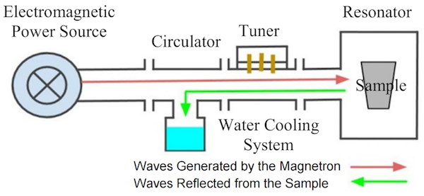
The setup for the microwave furnace. Image by N. Rezaii and J.P. Mai and taken from their COMSOL Conference 2016 Munich paper.
The microwave furnace consists of five parts:
- Magnetron core, which generates electromagnetic microwaves
- Waveguide, which transmits the microwaves into the resonator
- Resonator (also called the reaction chamber), which includes a crucible to hold the silicon sample
- Tuner, which improves the absorption of the microwaves
- Circulator, which keeps the magnetron from overheating by using a water bath to dissipate the reflective microwave energy
One advantage of an optimized microwave furnace design is that there is reduced heat loss. This is partially due to the selective heating, which heats materials on a volumetric heat input, leading to a temperature drop from the inside out. In addition, there’s less diffusion of the silicon’s impurities because the furnace has a faster warming time and shorter residence time.
To optimize the microwave furnace for solar-grade silicon production, JPM Silicon GmbH studied its internal processes with the COMSOL Multiphysics® software.
Simulating the Production of Solar-Grade Silicon in a Microwave Furnace
The research team set up their model to include the electromagnetic, chemical, and physical phenomena occurring within the microwave furnace. Since some materials have electromagnetic properties that are strongly temperature dependent, the model couples the electromagnetic field distribution and temperature field.
You can learn more about the model setup by reading the full conference paper “Multiphysics Modelling of a Microwave Furnace for Efficient Solar Silicon Production“.
It’s important to use chemically stable structural materials and an inert gas in the microwave furnace to avoid unwanted reactions. Also, the insulation materials must be effective in minimizing heat losses.
Electromagnetic Intensity and Distribution
The research team used the RF Module to simulate the electromagnetic intensity and distribution in the resonator and silicon sample. They used Maxwell’s equations to determine the propagation of the microwave radiation.
The electric field is higher at the height of the waveguide ports than at any other part of the reaction chamber. The field enhancement in the crucible’s core indicates that this is the optimal location for the crucible to be heated, as shown in the results below.
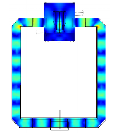
The distribution of the electric field in the resonator and waveguide. Image by N. Rezaii and J.P. Mai and taken from their COMSOL Conference 2016 Munich paper.
The researchers also wanted to see how varying the height of the insulation plate affects the operation of the furnace. They tested three different heights for the plate (which the crucible sits on top of) and reexamined the electric field. The different insulation plate heights include:
- 30 mm
- 40 mm
- 50 mm
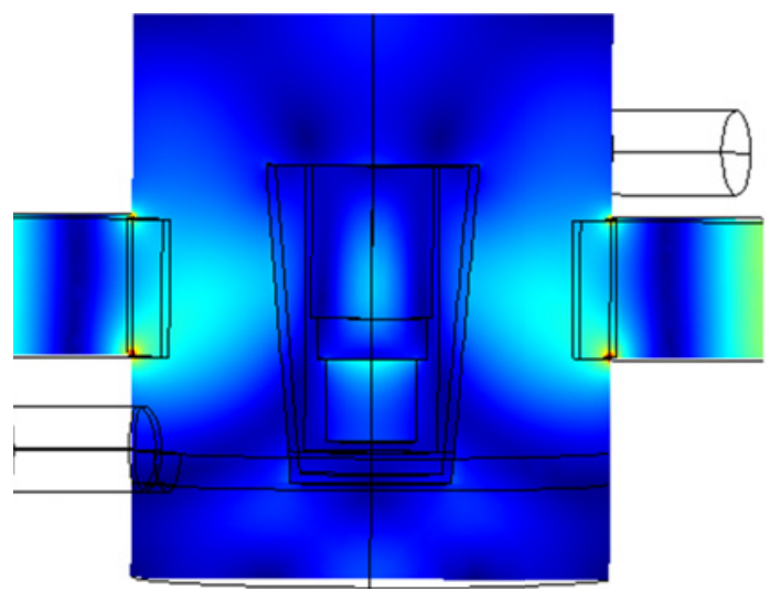
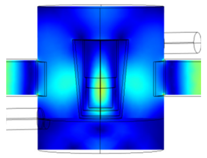
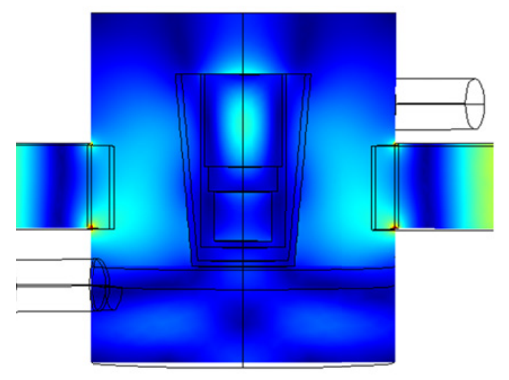
The distribution of the electric field when the height of the insulation plate is 30 mm (left), 40 mm (middle), and 50 mm (right). Images by N. Rezaii and J.P. Mai and taken from their COMSOL Conference 2016 Munich paper.
The simulation results show that the 40-mm insulation plate performs best. The electric field is focused at the center of the crucible, thus on the silicon sample.
Gas Flow Velocity Distribution
The CFD Module solves for the Navier-Stokes equations, allowing the researchers to find the gas flow velocity distribution. The gas flows from the inlet over the surface of the silicon sample, rather than having a homogeneous velocity. The wall then deflects the flow toward the outlet. The simulation shows that only a slight gas flow exists near the waveguide ports as well as near the top and bottom walls.
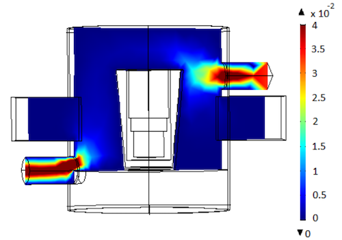
The distribution of gas velocity in the resonator. Image by N. Rezaii and J.P. Mai and taken from their COMSOL Conference 2016 Munich poster.
Heat Distribution
To analyze how well the electromagnetic waves heat the silicon sample, the research team examined the heat distribution in the resonator. Their model includes forced heat equations to calculate conduction, convection, and radiation from solids and liquids (Planck’s radiation law) as well as gases (Stefan-Boltzmann law). The dissipated heat, solved with the RF Module, is used as a volumetric heat source. The gas velocity profile, calculated with the CFD Module, helps find the convective thermal losses.
As expected from the electromagnetics study, the hottest point in the resonator is at the crucible’s core. Further, the surrounding insulation layers don’t heat up as much, thanks to their lower thermal conductivity.
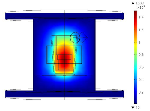
The distribution of heat in the resonator. Image by N. Rezaii and J.P. Mai and taken from their COMSOL Conference 2016 Munich poster.
By gaining insight into the internal processes of a microwave furnace, researchers from JPM Silicon GmbH were able to optimize their design and pave the way for efficient solar-grade silicon production.
Read More on Simulating Solar Applications
- Explore other examples of solar simulation applications in these blog posts:


Comments (0)