Plasmas can exhibit a large variety of properties. There are plasmas with high and low ionization degrees, as well as those with high and low pressures and hot and cold temperatures. Different equations and modeling approaches are necessary for each kind of plasma. This blog post gives an overview of the different plasma types and shows when to use which of the interfaces available in the Plasma Module.
Editor’s note: This post was updated on September 17, 2021, to reflect changes to interface names and new functionality.
Thermodynamic Equilibrium (TE)
If a plasma is located in a closed system, each process is in equilibrium with its reverse process (detailed balance) and the plasma is in thermodynamic equilibrium. Such a plasma can be characterized with a few parameters: The (typically very high) temperature, pressure, and number densities of each single species. The radiation corresponds to black-body radiation and can be described with Planck’s law. The population of the excited states obeys a Boltzmann distribution, while the velocity distribution is Maxwellian. The Saha equation gives the ionization degree.
Local Thermodynamic Equilibrium (LTE)
In a real plasma, deviations from equilibrium occur. For example, radiation escapes out of the plasma, disturbing the detailed balance. If the equilibrium still holds in a local sense, the plasma is in local thermodynamic equilibrium (LTE). The plasma can still be described (locally) by the above mentioned relations, with the exception of Planck’s law. Local thermodynamic equilibrium can only exist if the radiation processes can be neglected and the plasma is collision-determined. Therefore, a sufficiently high electron density is required.
Partial Local Thermodynamic Equilibrium (PLTE)
Electrons are more susceptible to the electric field than the heavy particles, due to their significantly lower mass. Electrons therefore gain more energy than the heavy particles per unit time. If the pressure is low or the electron density is small, the heavy particle temperature remains lower than the electron temperature. The plasma can no longer be described by a single temperature.
The energy difference between the ground state and the first excited state is normally large, whereas the energy difference between the excited states is small, especially in noble gases. If the electron density is sufficiently high, the excited states can be in equilibrium among each other (excluding the ground state). The velocity distribution within the different kind of species can still be Maxwellian (in spite of different temperatures). In such a case, the plasma is in partial local thermodynamic equilibrium (PLTE).
Non-Equilibrium Plasma
In non-equilibrium plasma, the heavy particle temperature is much lower than the electron temperature. The background gas in which the electrons and ions reside is more or less close to room temperature. There are considerable deviations from equilibrium. None of the aforementioned relations are still valid. In this case, a more elaborate approach is necessary.
Which Interface Do I Need for My Plasma Simulation?
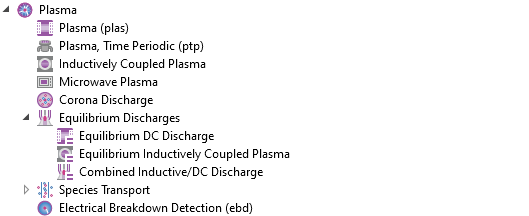
The Plasma Module brings with it several different interfaces. Here is a screenshot of the expanded Plasma node, to give you an overview:

Thermal Plasmas
The Equilibrium Discharges interfaces are suitable for modeling thermal plasmas. These plasmas can be considered as a conductive fluid mixture and may therefore be modeled using the magnetohydrodynamics (MHD) equations. MHD combines the Navier-Stokes, heat, and Maxwell’s equations to describe the motion of the conducting fluid in an electromagnetic field. The chemical composition of the plasma is neglected.
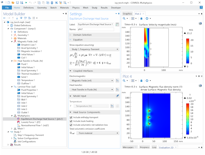
The following figure shows the Model Builder of an inductively coupled plasma torch. The Magnetic Fields interface is used to solve Ampère’s law. The Heat Transfer interface solves an energy balance equation and the Laminar Flow interface the Navier-Stokes equation. In addition, there is a Multiphysics node for the coupling terms.

Screenshot of the Model Builder for an inductively coupled plasma torch model. The Equilibrium Discharge Heat Source coupling settings are highlighted.
The Equilibrium Discharges interfaces assume that the plasma is fully ionized and that the plasma is under local thermodynamic equilibrium (LTE) conditions.
The Equilibrium DC Discharge interface is used to study equilibrium discharges that are sustained by a static or slow-varying electric field where induction currents and fluid flow effects are negligible.
The Equilibrium Inductively Coupled Plasma interface is used to study equilibrium discharges that are sustained by induction currents, for example in inductively coupled plasma torches.
The Combined Inductive/DC Discharge interface is used to study equilibrium discharges that are sustained by induction currents and/or static or slow-varying electric field, such as in arc welding simulations, for instance.
Nonthermal Plasmas
The other interfaces are suitable for modeling nonthermal or nonequilibrium plasmas. Here, a fluid model with drift diffusion approximation is used. A mass conservation equation for each species, an energy balance equation for the electrons, and Poisson equation for the electric field are solved. Here, the plasma chemistry is an essential part of the model. Additionally, a subset of Maxwell’s equations can be solved to account for coupling with a magnetic field or electromagnetic wave.
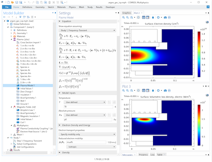
The following screenshot shows the Model Builder of an inductively coupled nonequilibrium argon plasma. You can find this model in the Model Library, too. The Plasma interface is used to model the complicated coupling between the electron and heavy species transport (via a drift diffusion approximation) and electrostatic field. Nodes that are used to describe plasma chemistry can be seen. The Magnetic Fields interface is used to solve Ampère’s law and simulate the electromagnetic field of the coil. There is a Multiphysics node for the corresponding coupling terms.

Screenshot of the Model Builder for a GEC reactor model with inductively coupled argon plasma. Plasma model settings are highlighted.
The Plasma interface is used to study discharges that are sustained by a static electric field. The Plasma, Time Periodic interface is used to study capacitively coupled discharges that are sustained by a time-varying electrostatic field. The Inductively Coupled Plasma interface is used to study discharges that are sustained by induction currents. The Microwave Plasma interface is suitable for studying discharges that are sustained by electromagnetic waves (wave-heated discharges). The Corona Discharge and Electrical Breakdown Detection interfaces are useful for fast engineering estimation of corona and streamer discharge occurrence, respectively.
Additional Resources
- Get started creating plasma simulations with a tutorial model from the online Model Gallery
- Watch an intro video about key features of the Plasma Module
- Contact technical support if you have any questions about your particular case


Comments (7)
Dwekat
June 9, 2015Thank you Annette Meiners , that was very helpful .
However you didn’t explain much about the Capacitively coupled plasma and the DC discharge .
which after reading your article i became confused about my SF6 circuit-breaker electric arc model ! which of those you recommend ?
Regards ;
Babak Porkar
October 7, 2016Thanks a lot Annette for your very useful blog.
Are any example model develops in COMSOL addressing “Combined Inductive/DC Discharge” or “DC Discharge” ?
Best
Caty Fairclough
November 3, 2016Hi Babak,
Thank you for your interest in this blog post! I believe you may find the DC Glow Discharge tutorial helpful.
If not, feel free to reach out to COMSOL Support.
Online support center: https://www.comsol.com/support
Email: support@comsol.com
Thank you!
Best,
Caty
Ruslan Medvedev
May 3, 2017Dear Annette.
Why you consider the Inductively coupled plasma is in local thermodynamic equillibrium?
The currents and electric fields in ICPs are oscillated with MHz frequencies.
It is necessary to compare the times of free paths of particles with time of varying the electromagnetic fields each time. For example under atmospheric pressure these times are much smaller then the periods of RF fields but if we decrease the pressure to about 10^-5 atm these times will be comparable and plasma will not be in LTE. Also it should be accounted for the characteristic times of spontaneous emissions by excited atoms which are 10^-8 s in order.
Moreover it should be kept in mind that the parameters of ICP strongly depend on the value of external electromagnetic field in other words the phase of RF field!
Annette Pahl
May 17, 2017 COMSOL EmployeeDear Ruslan,
In this blog post two icp models are cited:
The first model– the icp torch – works under atmospheric pressure. Here LTE is assumed. The second model shown here – the argon gec icp – is driven with a pressure of 0.02 Torr. This is clearly a non-thermal plasma and thus no LTE approximation is made.
You can find these models in our Application Library. Here more information about the parameters and underlining equations are given.
Best
Annette
Kristov George
June 21, 2017Hi Annette,
I am curious which Plasma module you would recommend for simulating the Ionic Wind phenomena?
Best,
Kristov
Bridget Cunningham
July 19, 2017 COMSOL EmployeeHi Kristov,
Thank you for your comment.
Modeling ionic wind is on the more difficult side with the current capabilities of the Plasma Module. We do, however, have a few simple models available of corona discharge, which produce ionic winds: https://www.comsol.com/models?q=corona%20discharge.
We encourage you to check in with your COMSOL representative in regards to your specific application.