Structural Mechanics Module Updates
New Electromechanics Multiphysics Interfaces
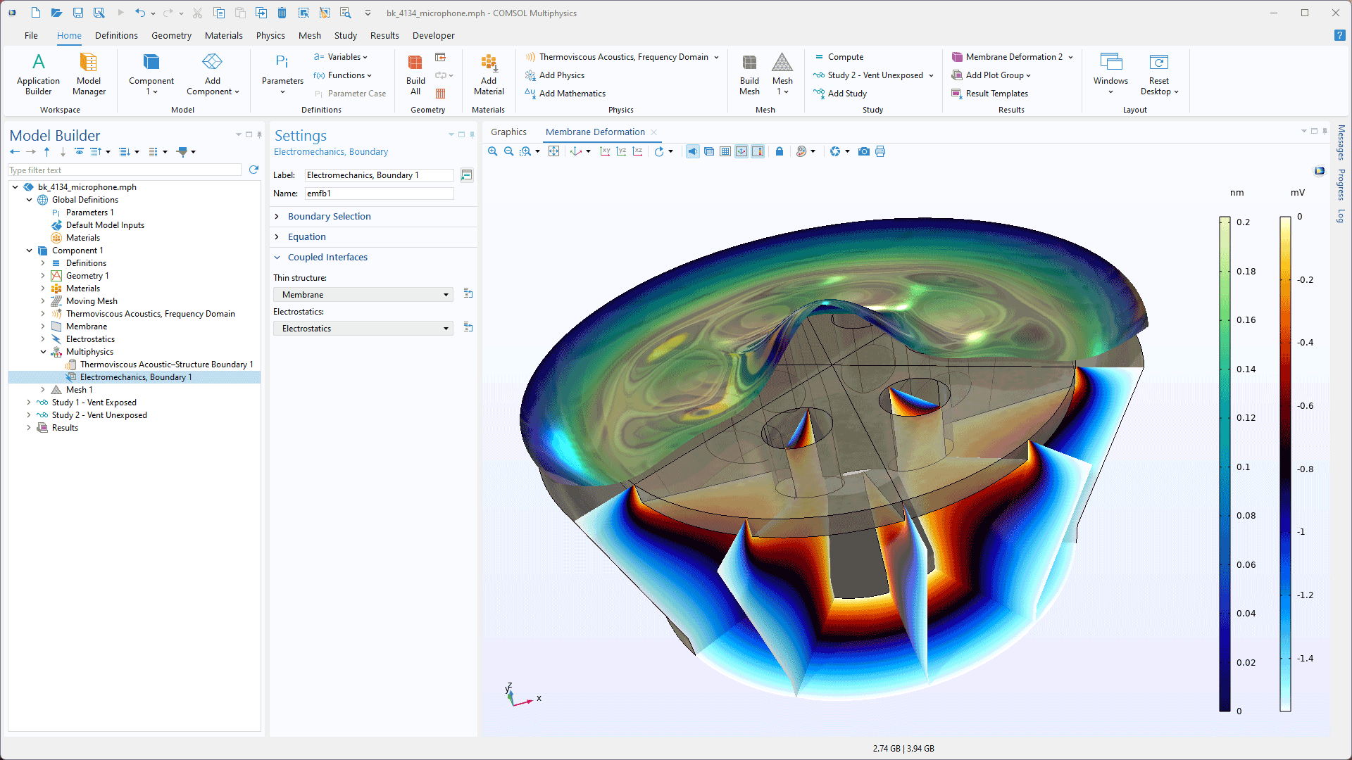
The new Electromechanics, Shell and Electromechanics, Membrane interfaces simplify modeling the deformation of thin structures, such as microphone membranes, influenced by electrostatic forces. These interfaces automatically include the Electromechanics, Boundary multiphysics coupling for seamless integration with shell or membrane elements, and they use the Electrostatics interface to model the electric field. Demonstrated in the Brüel & Kjær 4134 Condenser Microphone and Axisymmetric Condenser Microphone tutorial models, these interfaces require the AC/DC Module or MEMS Module in addition to the Structural Mechanics Module.
Shrinkage and Swelling Multiphysics Coupling
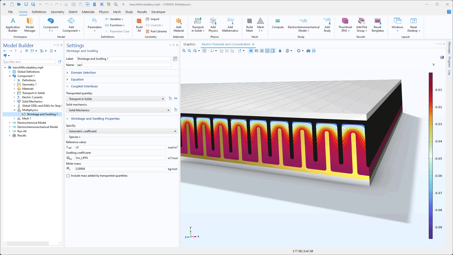
For modeling volume changes induced by diffusion, a new Shrinkage and Swelling multiphysics coupling that bidirectionally connects the Transport in Solids and Solid Mechanics interfaces has been added. This new coupling can be used to simulate the effects of concentration changes on volume and how stresses may affect diffusion. This is useful, for example, in batteries, where very large volume changes can occur due to ion transport. This new feature can be seen in the following tutorial models:
Simplified Modeling of Fasteners
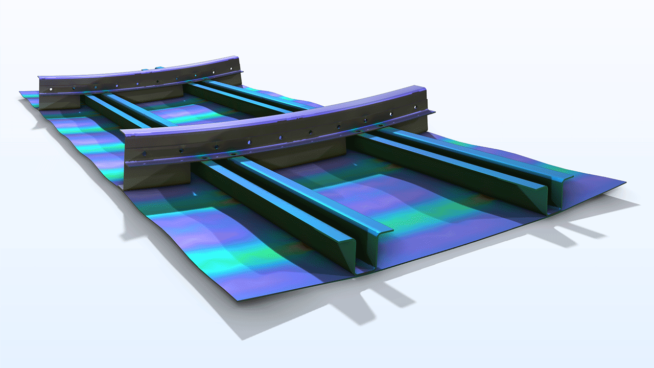
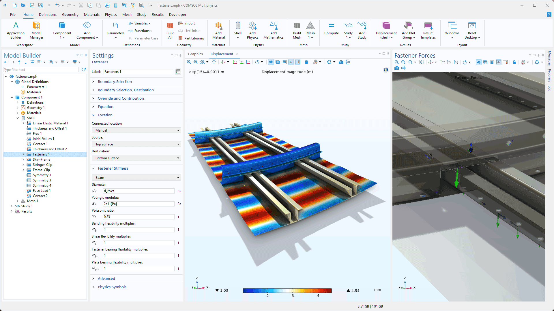
For structures connected by a large number of fastening elements such as rivets or bolts, manual modeling of each element can become time consuming. To help alleviate this, a new Fasteners feature has been added to the Shell interface. This feature automatically detects paired circular holes on parallel shell boundaries and connects them. The stiffness of the connection will take properties such as material data, fastener diameter, and plate thickness into account. It is also possible to compute safety factors for the fasteners based on user-defined expressions. The new Postbuckling Analysis of an Aircraft Fuselage tutorial model showcases this feature.
Spot Welds
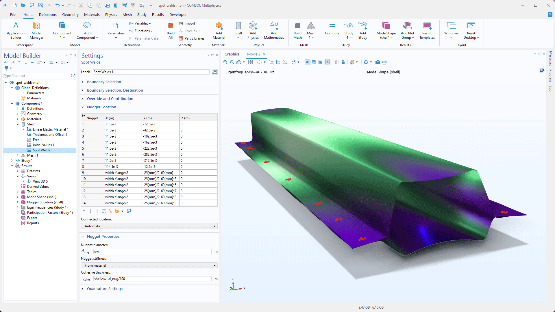
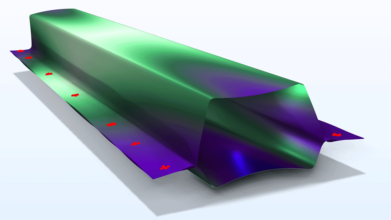
For the Shell interface, a new Spot Welds feature has been added that makes it easier to model structures connected by a large number of spot welds. The locations of the weld nuggets are given as a list that can be imported from a text file. The implementation is independent of the mesh on the connected shell boundaries and includes a user-controlled stiffness. The forces and moments transferred by each nugget can also be evaluated in graphic and tabular form. The new Spot-Weld Connection in a Double Hat Beam tutorial model showcases this new feature.
Contact Formulation for Interior Boundaries
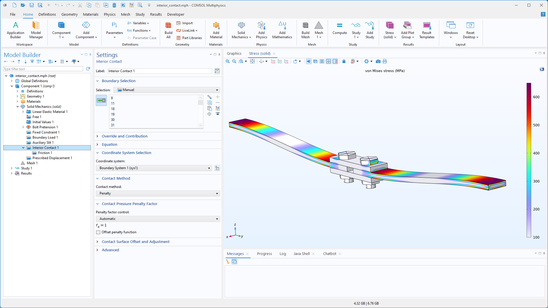
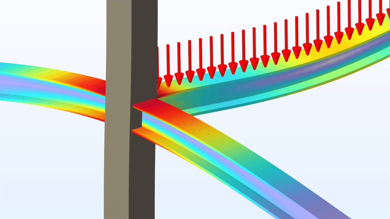
A new Interior Contact feature has been added to the Solid Mechanics interface that makes it possible to include contact conditions such as friction, adhesion, and decohesion to internal boundaries. With this formulation, contact pairs and assemblies are not required and the analysis can be geometrically linear. This feature can be used for modeling applications such as bolted joints and boundaries separated by decohesion. The Mixed-Mode Debonding of a Laminated Composite and Vibration of a Squeezed Plate tutorial models have been updated to showcase this new feature.
Fitting of Viscoelastic Data
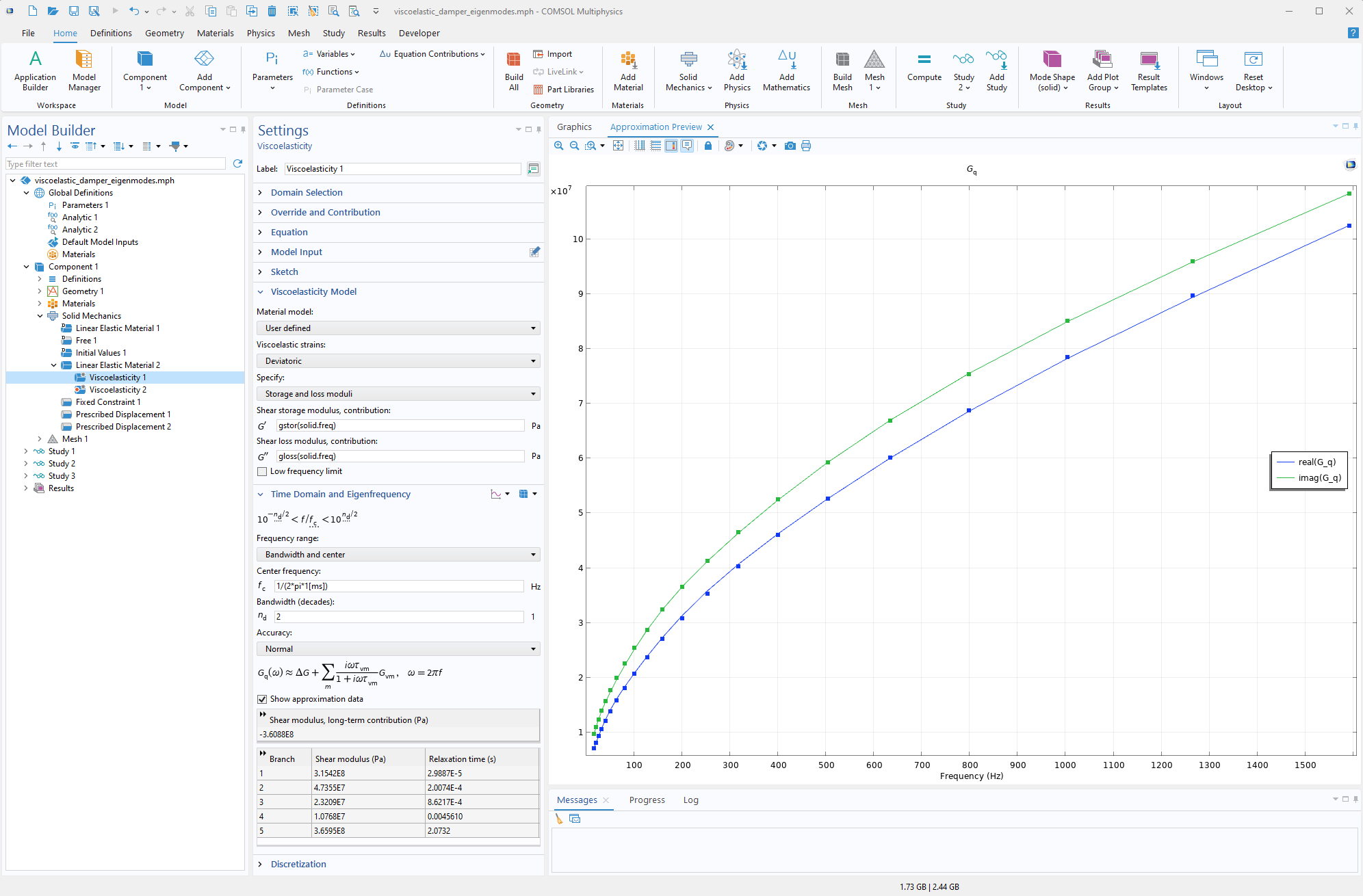
Properties for viscoelastic materials are often measured in the frequency domain and are typically available as frequency-dependent storage and loss moduli or approximated using fractional derivative models. In this version, a new capability has been added to the Viscoelasticity feature that maps such data to time-domain functions using a partial fraction fit. This allows users to perform time-dependent simulations of viscoelastic materials, regardless of the original form of the material properties. This new addition can be seen in the Eigenmodes of a Viscoelastic Structural Damper tutorial model.
Visualization of 3D Beams and Pipes
It is now possible to achieve a full 3D visualization for beam and pipe elements using the new Beam and Pipe dataset types. These datasets can be used, for example, to visualize stress distribution and variables over the cross section. The built-in cross section types, Rectangle, Circular, Box, Pipe, H-profile, T-profile, U-profile, C-profile, and Hat, are supported. The following tutorial models showcase this new capability:
Stabilization in the Membrane Interface
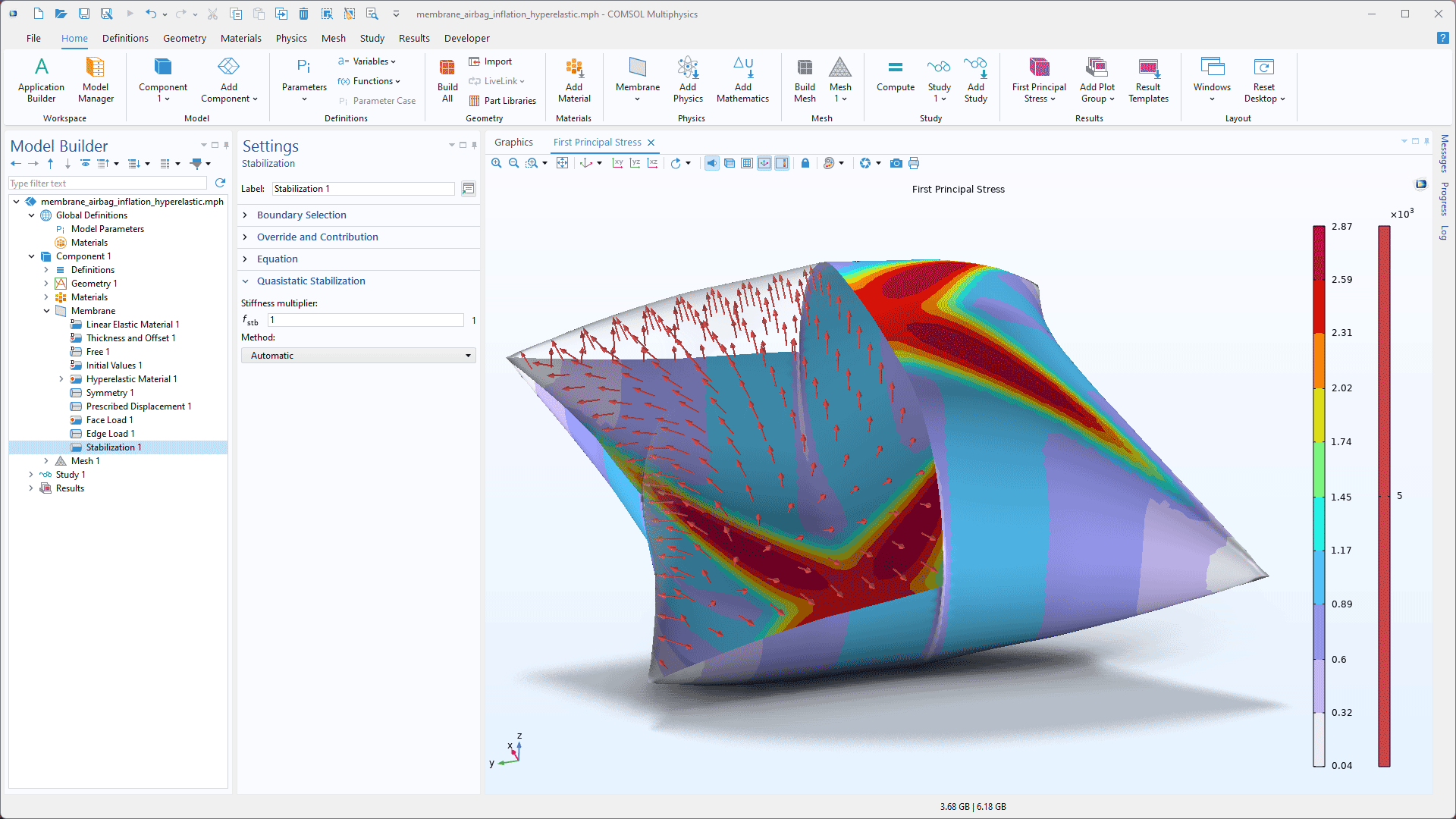
The out-of-plane stiffness for membranes is controlled by the in-plane tension. As an effect, it is common that membranes are numerically unstable in an initial stress-free configuration, before external loads have been added. With the new Stabilization feature in the Membrane interface, it is possible to achieve automatic stabilization during the first few iterations before the structure has obtained its correct physical and numerical stiffness from the induced loading. The following tutorial models demonstrate this feature:
- membrane_airbag_inflation
- membrane_airbag_inflation_hyperelastic
- membrane_torsion
- membrane_uniaxial_stretching
- vibrating_membrane
Random Particulate Composite Add-In
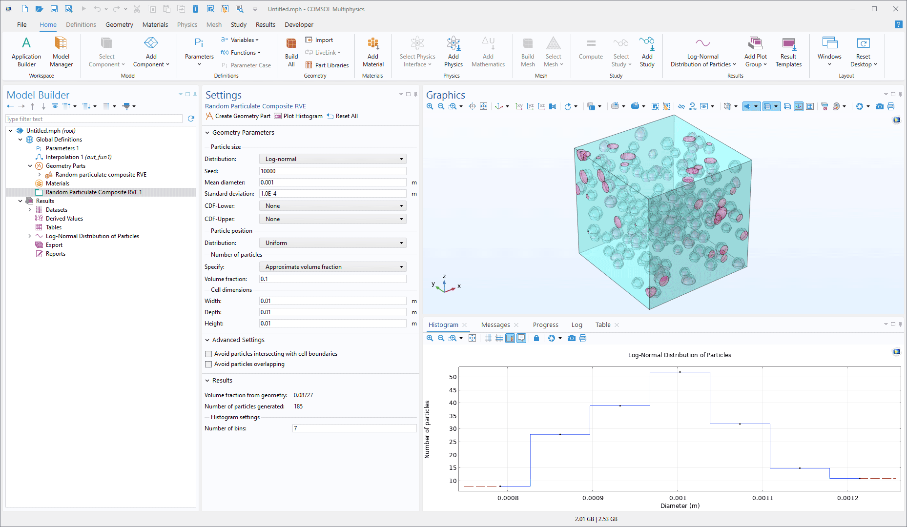
A new add-in to generate geometry parts for random particulate composites has been added under the COMSOL Multiphysics branch of the Add-in Libraries. The add-in can be used to create spherical particles inside a rectangular block, where their positions and size are fixed or randomly distributed based on different probability distributions.
Composites Material Library Folder
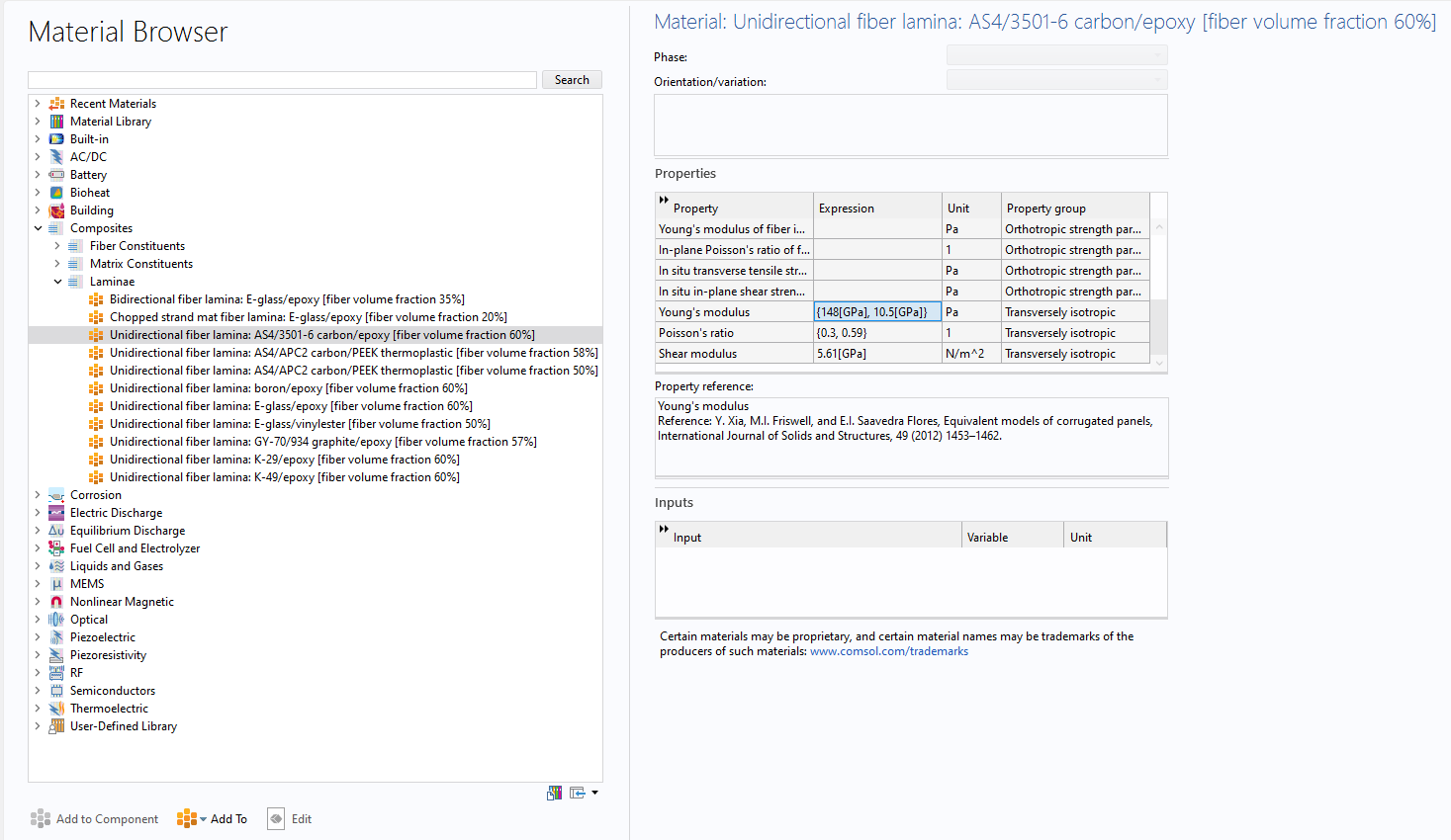
The new built-in folder for Composites is divided into three groups of materials: fiber constituents, matrix constituents, and laminae. This feature makes it easier to set up models with common types of composite plies. You can view these new materials being used in the following tutorial models:
- composite_cylinder_micromechanics_and_stress_analysis
- composite_multiscale
- composite_wheel_rim
- ply_drop_off_in_a_composite_panel
- layered_shell_structure_connection
- stacking_sequence_optimization
- progressive_delamination_in_a_laminated_shell
- homogenization_of_periodic_microstructures
New Tutorial Models
COMSOL Multiphysics® version 6.3 brings several new tutorial models to the Structural Mechanics Module.
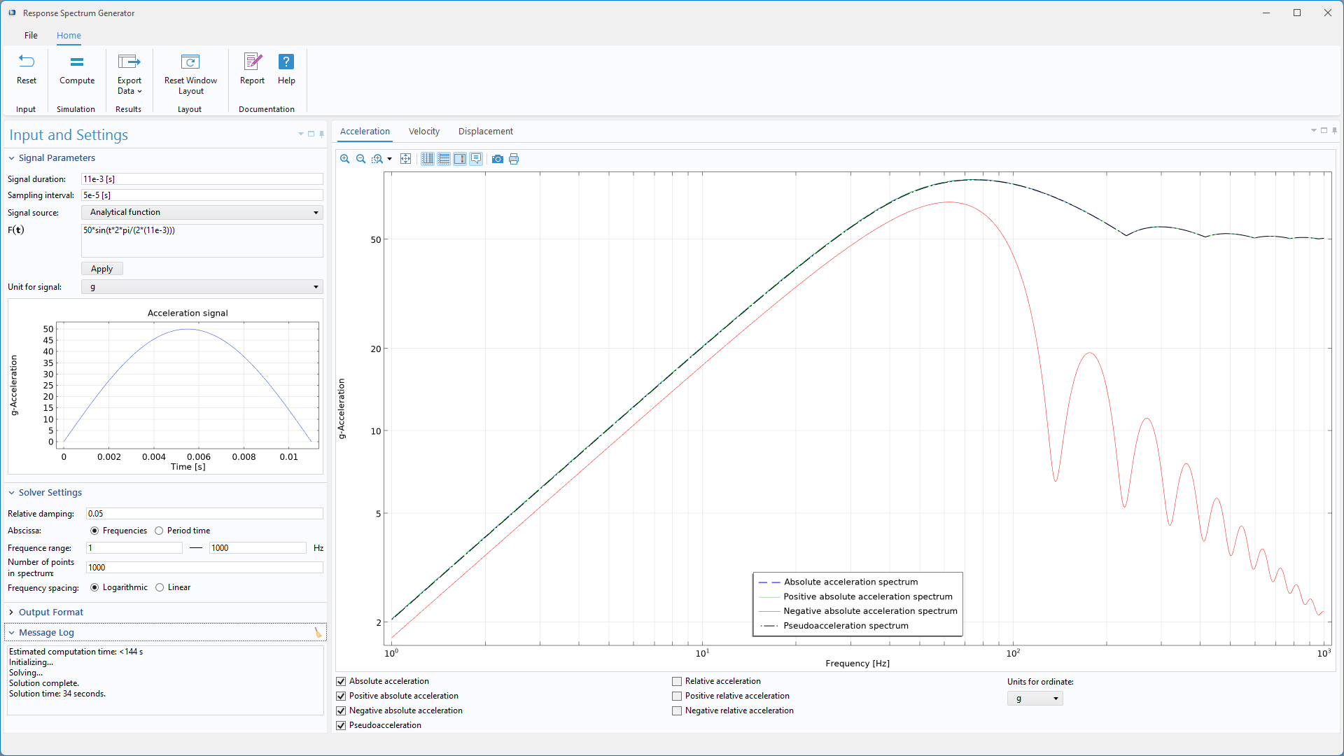
Response Spectrum Generator
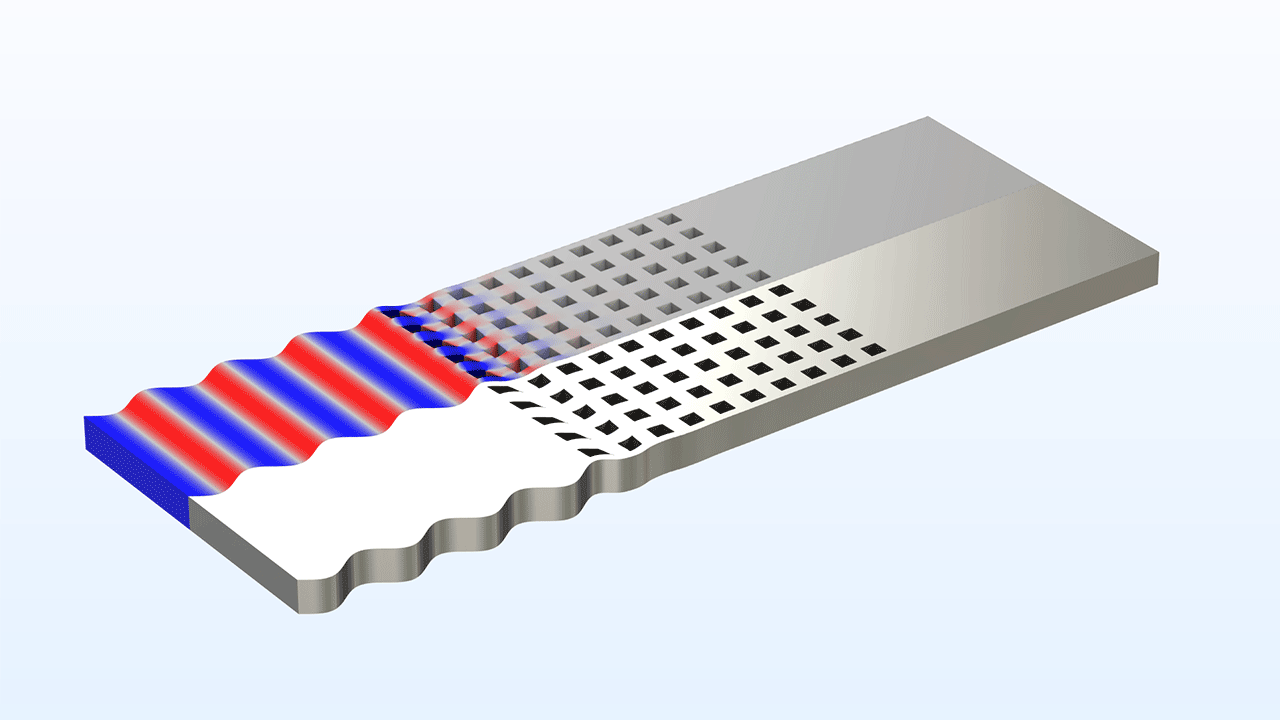
Phononic Crystal
Postbuckling Analysis of an Aircraft Fuselage
Spot-Weld Connection in a Double Hat Beam
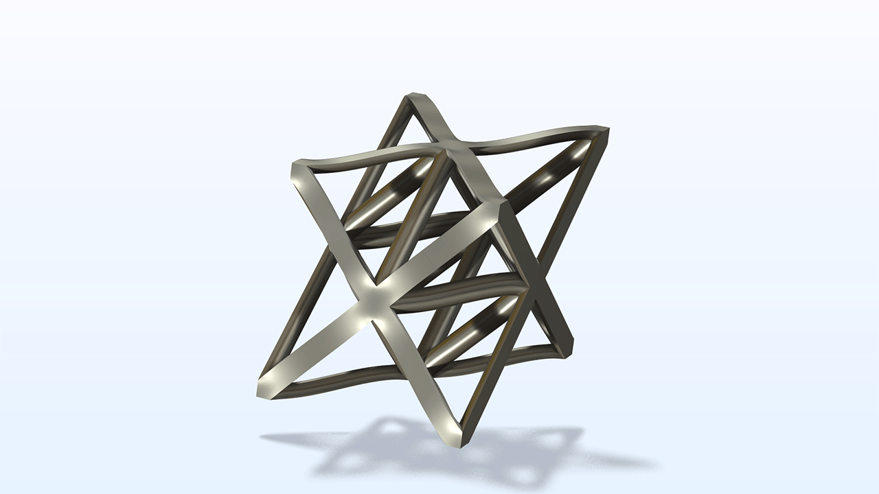
Micromechanical Model of an Octet-Truss Lattice Cell
micromechanical_model_of_an_octet_truss_lattice_cell
Download from the Application Gallery
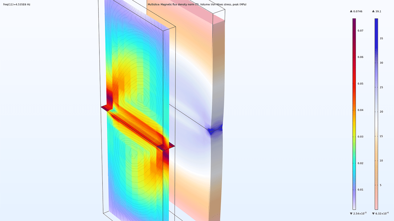
Piezomagnetic Cell Rover*
Application Library Title:
piezomagnetic_cell_rover
Download from the Application Gallery
*Requires the AC/DC Module

