Fuel Cell & Electrolyzer Module

Design and Analyze Fuel Cells and Electrolyzers

The Fuel Cell & Electrolyzer Module is an add-on to the COMSOL Multiphysics® software for gaining a deeper understanding of fuel cell and electrolyzer systems, which is useful for designing and optimizing the electrochemical cells. The types of systems that may be studied include proton exchange membrane fuel cells (PEMFCs), hydroxide exchange (alkaline) fuel cells (AFCs), and solid oxide fuel cells (SOFCs), as well as the corresponding water electrolyzer systems. The module accommodates all types of fuel cells and electrolyzers.

As with every add-on module in the COMSOL product suite, multiphysics capabilities are built into the module for including multiphase fluid flow, heat transfer, thermodynamics properties, and more.

Contact COMSOL
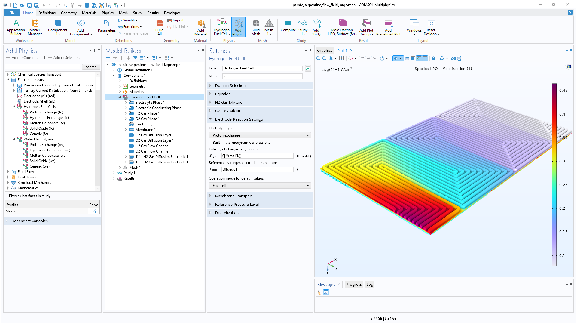
A PEM fuel cell model showing the gas flow fields in the rainbow color table.

Hydrogen Fuel Cells

The Fuel Cell & Electrolyzer Module features predefined formulations for the most common types of hydrogen fuel cell and accounts for the electrodes, electrolyte, and current collectors and feeders. Examples of fuel cell types that can be modeled are PEMFCs and high-temperature PEMFCs, anion exchange membrane fuel cells (AEMFCs), alkaline fuel cells (AFCs), phosphoric acid fuel cells (PAFCs), SOFCs, and molten carbonate fuel cells (MCFCs), to name a few.

Modeling and simulation can be used to predict the current and potential distribution, chemical species distribution, and temperature distribution in a fuel cell. In this way, the cell can then be designed for the best possible utilization and operation for a given set of conditions. Important aspects are the removal of water and avoiding nonuniform utilization of the cell, which may result in poor performance and decreased lifespan. Additionally, microscopic aspects of the gas diffusion electrodes and the active layers can be studied, such as catalyst loading, particle size distribution, and bimodal pore distribution.
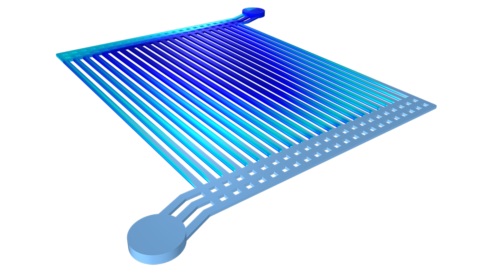
Water Electrolyzers

Electrolyzers can be used to locally produce hydrogen from electricity through water electrolysis. This hydrogen can be stored and converted back to electricity using fuel cells, when there is a demand and capacity in the grid.

The design of a water electrolyzer is similar to that of a hydrogen fuel cell, with three key differences: the current runs in the reverse direction, the cathode is the negative electrode, and the anode is the positive electrode. The models within the Fuel Cell & Electrolyzer Module involve the description of the gas diffusion electrodes, the active layer, the electrolyte separator, and the bipolar plates with the channels.

Industrial Electrolyzers

The functionality of the Fuel Cell & Electrolyzer Module is not limited to water electrolyzers: Any electrochemical cell or electrolyzer can be modeled. This functionality includes the ability to describe gas evolution and laminar multiphase flow. For systems such as chlorate electrolysis and the chlor-alkali membrane process, the module can be combined with the CFD Module to also treat turbulent flows.

Features and Functionality in the Fuel Cell & Electrolyzer Module

Perform various analyses for fuel cells and electrolyzers with the COMSOL® software.

A close-up view of the COMSOL Multiphysics UI showing the Model Builder and the Graphics window for a 3D PEMFC model.

Built-In User Interfaces

COMSOL Multiphysics® provides users with prebuilt user interface combinations that define a set of equations together with settings for mesh generation, solvers, and results. For the Fuel Cell & Electrolyzer Module, these combinations include hydrogen fuel cells and water electrolyzers.

By selecting any of the Hydrogen Fuel Cell and Water Electrolyzers interfaces, the transport and reaction properties for the oxygen and hydrogen gas diffusion electrodes are defined automatically. Only the domains for the electrodes, electrolyte, separator, and gas channels need to be selected. Chemical species and additional reactions can also be added to the oxygen and hydrogen gas diffusion electrodes, such as steam or carbon dioxide. The model equations solve for the electrode (electronic conduction) and electrolyte phase (ionic conduction) potentials as well as for the mole fractions of the gas mixtures in the system.

A close-up view of the Model Builder with the Concentrated Electrolyte Transport node highlighted and a 1D plot in the Graphics window.

Concentrated Electrolyte Transport

The Concentrated Electrolyte Transport interface can be used for modeling transport in electrolyte solutions containing an arbitrary number of charged and uncharged species. This electrochemistry interface is based on concentrated solution theory, where the transport equations are defined using binary Maxwell–Stefan diffusion coefficients under the assumption of local electroneutrality. In contrast to the Nernst–Planck equations, concentrated solution theory does not assume that electrolyte species are diluted in a neutral solvent of constant concentration. Typical applications include ionic liquids, molten salts, and highly concentrated solutions with significant concentration gradients of the charge-carrying species. This interface is well suited for analyzing multicomponent transport behavior in advanced electrochemical systems.

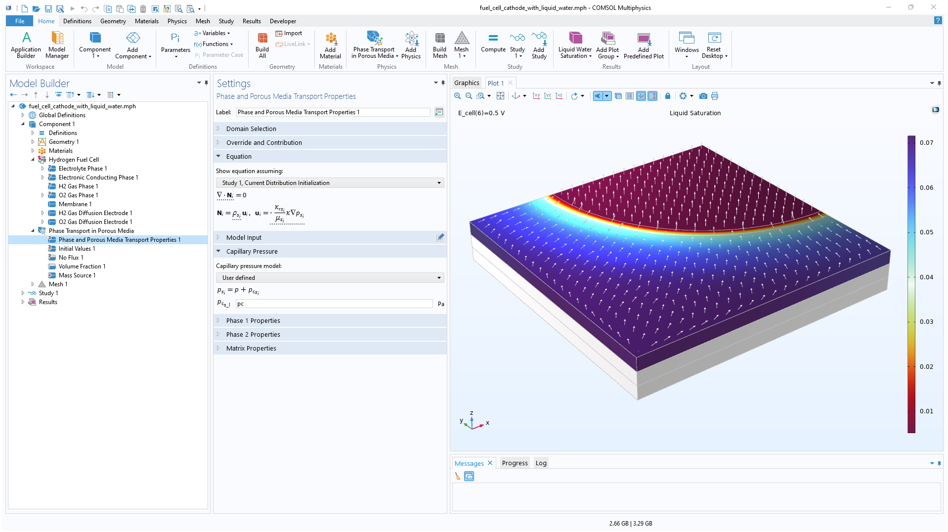
A close-up view of the COMSOL Multiphysics UI showing the Model Builder and the Graphics window for a fuel cell cathode model.

Multiphase and Single-Phase Flow in Free and Porous Media

One of the specific phenomena in low-temperature fuel cells and water electrolyzers is the concurrent transport of liquid and gaseous water (steam). In fuel cells, the flow needs to drive water out of the cell as well in order to avoid flooding of the electrodes. Similarly, in water electrolysis, inadequate transport of the produced gas may render parts of the cell inactive. In both cases, it is important to model two-phase flow in the porous electrodes and in the open channels.

The Fuel Cell & Electrolyzer Module features the mixture, bubbly flow, and Euler–Euler models for dispersed multiphase flows, as well as phase transport in porous media. These features enable the modeling of multiphase flow in porous media (electrodes) as well as in open free media (channels). For more information on these multiphase flow models, view the CFD Module.

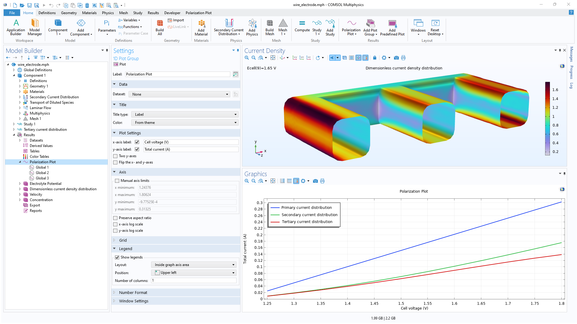
A close-up view of the COMSOL Multiphysics UI showing the Model Builder and the Graphics window for a 1D plot of primary, secondary, and tertiary current distribution.

Primary, Secondary, and Tertiary Current Distribution

The space-dependent simulations (1D, 2D, and 3D) can account for ohmic losses (primary), ohmic and activation losses (secondary), as well as ohmic, activation, and mass transport losses (tertiary). For tertiary current distributions, it is possible to define systems with supporting electrolytes, dilute electrolytes, and concentrated electrolytes. The transport equations — the Nernst–Planck equations — can be combined with the electroneutrality condition or Poisson's equation.

The electrode kinetics can be defined using the Tafel equation, the Butler–Volmer equation, or arbitrary functions of the overpotential and the concentration of chemical species. Multiple reactions may be defined on an electrode surface (an arbitrary number).

The current distribution interfaces can be used in combination with porous electrodes, gas diffusion electrodes, and planar electrodes.

A close-up view of the COMSOL Multiphysics UI showing the Model Builder and the Graphics window for an SOFC unit cell model.

Gas Diffusion Electrodes

Modeling gas diffusion electrodes (GDEs) in the Fuel Cell & Electrolyzer Module is very straightforward. The transport equations in the gas phase and in the pore electrolyte are automatically defined in the user interface based on the boundary conditions added. The software contains separate domain features for defining the hydrogen and oxygen electrodes. The main electrode reactions are predefined, with the option to change the kinetics and add parasitic reactions or other reactions.

The transport of species in the gas phase is automatically coupled with the transport in the gas channels. The fluid flow is defined for the gas channel and for the porous structure using the Brinkman equations to model fully coupled free and porous media flow.

The charge balance in the electrolyte (separator) and the pore electrolyte (the electrolyte in the active layer or in the GDE) are also defined. They are automatically coupled to the transport equations in the gas phase through the electrochemical reactions and Faraday's law.

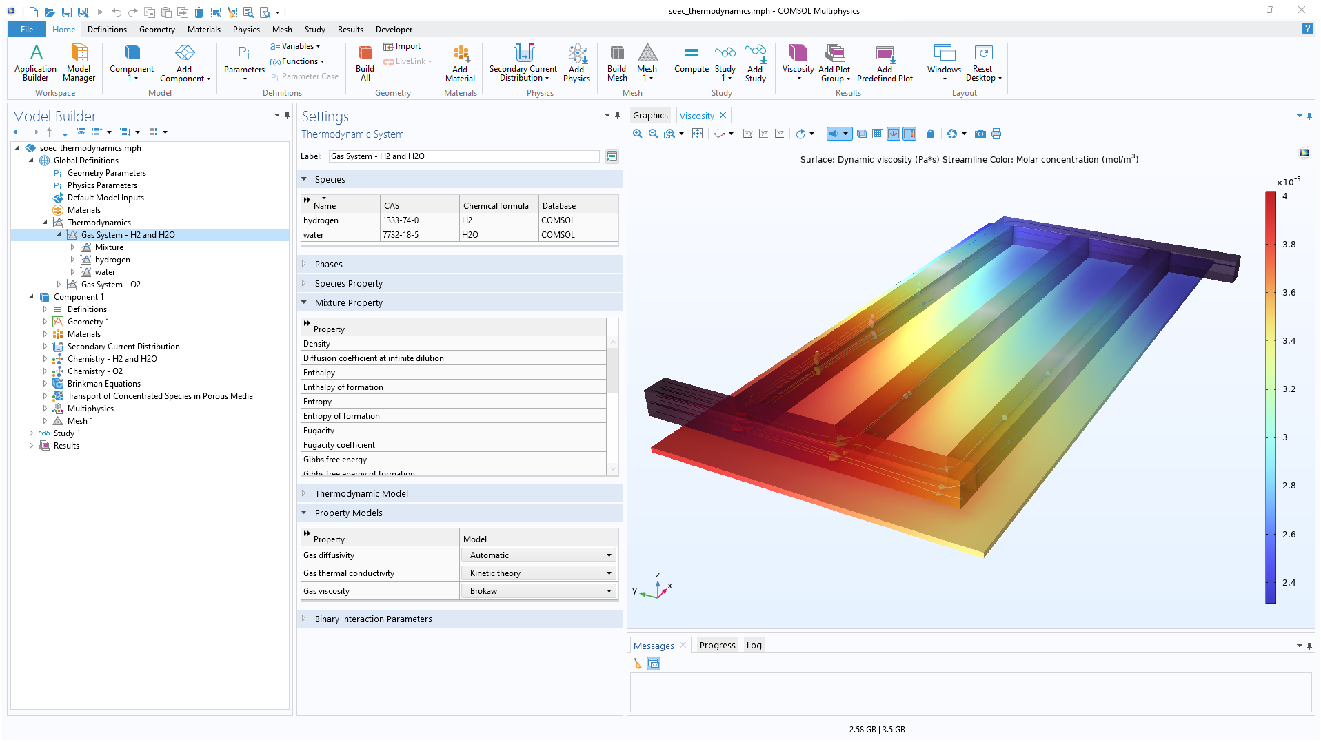
A close-up view of the COMSOL Multiphysics UI showing the Model Builder and the Graphics window for an SOEC model.

Built-In Thermodynamics

The content of the gas mixtures in the hydrogen and oxygen electrodes may vary for different processes and different operating conditions. The Fuel Cell & Electrolyzer Module contains a built-in thermodynamic properties database for hydrogen mixtures and oxygen mixtures. For instance, nitrogen, water, carbon dioxide, or carbon monoxide can be implemented as additional species for a hydrogen mixture in order to model byproducts from reforming reactions. The same additional species are available for an oxygen mixture. When the composition is selected and the reference partial pressures are defined, the software can compute the equilibrium electrode potential for the hydrogen and oxygen electrode reactions and thereby the equilibrium potential for the cell.

Every business and every simulation need is different.

In order to fully evaluate whether or not the COMSOL Multiphysics® software will meet your requirements, you need to contact us. By talking to one of our sales representatives, you will get personalized recommendations and fully documented examples to help you get the most out of your evaluation and guide you to choose the best license option to suit your needs.

Just click on the "Contact COMSOL" button, fill in your contact details and any specific comments or questions, and submit. You will receive a response from a sales representative within one business day.

Next Step

Request a Software Demonstration